
What is Booting?
You must have heard this word a lot.
The term “booting” originates from the phrase “pulling oneself up by one's bootstraps”. This phrase refers to a seemingly impossible task, as pulling oneself up by bootstraps would defy the laws of physics. However, in the context of computers, “Bootstrapping” refers to the process of starting up a computer and loading its operating system.
What happens When you start the computer
When you start a computer, it goes through a series of steps known as the boot process. Here is top level view of things happening in the booting:
1. Power-On Self-Test (POST):
- When you press the power button, the computer's hardware components are powered on.
- The system's firmware, either BIOS (Basic Input/Output System) or UEFI (Unified Extensible Firmware Interface), conducts a Power-On Self-Test (POST).
- POST checks the hardware components such as the CPU, RAM, storage devices, and other peripherals to ensure they are functioning properly.
- If the POST detects any issues, it typically produces error messages or emits beep codes to indicate the problem.
2. BIOS/UEFI Initialization:
- After the hardware checks are completed, the system's firmware initializes the hardware components based on the configuration stored in the BIOS/UEFI settings.
- The firmware initializes the CPU, memory (RAM), storage devices, and other peripherals.
- The firmware also performs a check of connected devices and allocates system resources accordingly.
3. Boot Device Selection:
- The firmware locates the boot device specified in the BIOS/UEFI settings. This is usually the hard drive, SSD, or another storage device where the operating system is installed.
- If the specified boot device is not available, the firmware tries to boot from other available devices according to the boot order specified in the BIOS/UEFI settings.
4. Bootloader Execution:
- Once the boot device is selected, the firmware loads and executes the bootloader.
- The bootloader is a small program stored in the Master Boot Record (MBR) or EFI System Partition (ESP) of the boot device.
- The bootloader's primary function is to load the operating system kernel into memory.
5. Operating System Kernel Loading:
- The bootloader loads the operating system kernel into memory.
- The kernel is the core component of the operating system that manages system resources such as memory, CPU, and peripheral devices.
- Once the kernel is loaded into memory, it takes over control of the system.
6. Operating System Initialization:
- The kernel initializes the rest of the operating system.
- This includes setting up device drivers, initializing the file system, and starting essential system services.
- Once the initialization is complete, the operating system is ready for use.
7. User Space Initialization:
- After the operating system is initialized, user-space processes and services are started.
- This includes launching the graphical user interface (GUI) or command-line interface (CLI) and starting user applications.
8. User Login:
- Finally, the operating system is fully booted, and the user is presented with a login screen (if applicable).
- The user can then log in and start using the computer.
Booting Process from Engineers POV
1 CPU Reset
- The processor starts in real mode.
As soon as the CPU receives power. The BIOS is executed directly from ROM. The ROM chip is mapped to a fixed location in the processor's memory space (this is typically a feature of the chipset). When the x86 processor comes out of reset, its Instruction Pointer (IP) points to a specific “Reset Vector”, which is a predetermined memory address where the CPU starts executing instructions after a reset.
However, executing directly from ROM is quite slow, so usually one of the first things the BIOS does is to copy and decompress the BIOS code into RAM, and it executes from there. Of course, the memory controller must be initialized first! The BIOS takes care of that beforehand.
There is another theory for it:
When the processor first starts up, it is suffering from amnesia; there is nothing at all in the memory to execute. Of course processor makers know this will happen, so they pre-program the processor to always look at the same place in the system BIOS ROM for the start of the BIOS boot program. The motherboard ensures that the instruction at the reset vector is a jump to the memory location mapped to the BIOS entry point.
In computing, the reset vector is the default location a central processing unit will go to find the first instruction it will execute after a reset. The reset vector is a pointer or address, where the CPU should always begin as soon as it is able to execute instructions. The address is in a section of non-volatile memory initialized to contain instructions to start the operation of the CPU, as the first step in the process of booting the system containing the CPU.
- x86 family (Intel):
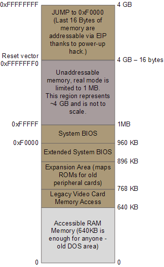
- The reset vector for the Intel 8086 processor is at physical address
FFFF0h(16 bytes below 1 MB). The value of the CS register at reset isFFFFhand the value of the IP register at reset is0000hto form the segmented addressFFFFh:0000h, which maps to physical addressFFFF0h.
- The reset vector for the Intel 8086 processor is at physical address
An Example of the relevant memory regions is shown below:
2 BIOS Initialization
The CPU then start executing BIOS code, which initializes some of the hardware in the machine. Afterwards the BIOS kicks off the Power-on Self Test (POST) which tests various components in the computer. Like Lack of a working video card fails the POST process and causes the BIOS to halt and emit beeps to let you know what's wrong, since messages on the screen are not an option.
Other POST failures, like a missing keyword, lead to halts with an error message on the screen.
After the POST the BIOS wants to boot up an operating system, which must be found somewhere: hard drives, CD-ROM drives, floppy disks, etc. The actual order in which the BIOS seeks a boot device is user configurable. The Boot order is stored in the BIOS configuration, controlling which devices the BIOS attempts to boot from a hard drive, the BIOS tries to find a boot sector. If there is no suitable boot device the BIOS halts with a complaint like “Non-System Disk or Disk Error.” A dead hard drive might present with this symptom. Hopefully this doesn’t happen and the BIOS finds a working disk allowing the boot to proceed.
3 Master Boot Record (MBR)
When the computer boots, the BIOS doesn't know how to load the OS, so it delegates that task to the boot sector. Thus, the boot sector must be placed in a known, standard location. That location is the first sector of the disk (cylinder 0, head 0, sector 0) and it takes 512 bytes.
The BIOS now reads the first 512-byte sector (sector zero) of the hard disk. This is called the Master Boot Record and it normally contains two vital components: a tiny OS-specific bootstrapping program at the start of the MBR followed by a partition table for the disk. The BIOS however does not care about any of this: it simply loads the contents of the MBR into memory location 0x7c00 and jumps to that location to start executing whatever code is in the MBR.

MBR Contains:
- MBR partition table
- 446 bytes of bootloader code
- Disk signature
- Magic number (0x55AA), the final two bytes of the first sector are
0x55and0xaa, which designates to the BIOS that this device is bootable.
|-----------------------|-----------------------------------------------|
| MBR Partition Table   | (64 bytes)                                    |
|-----------------------|-----------------------------------------------|
| Bootloader Code       | (446 bytes)                                   |
|-----------------------|-----------------------------------------------|
| Disk Signature        | (4 bytes)                                     |
|-----------------------|-----------------------------------------------|
| Magic Number (0x55AA) | (2 bytes)                                     |
|-----------------------|-----------------------------------------------|
Memory Segmentation:
8086 Microprocessor has a memory size is 1MB i.e., 2 rise to 20. Thus we use a 20-bit physical address (actual address) to satisfy 1MB memory with unique address. The unique address of every memory location is called a physical address. The physical address is 20 bit, and it is not a byte compatible number. 20 bit would 2 and half bytes (8 bit * 2 + 4), which means half a byte, will be wasted in every instruction. Thus there will be a massive wastage of memory because of the remaining half byte.
Why we didn't need segmentation in 8085 microprocessor?
This problem didn’t aroused in 8085(previous microprocessor) because 8085 has a 16-bit address bus, which can address up to 64KB. We know, a 16-bit address is a byte compatible number. 8086 has 1MB memory so that we have more space.
- The 8086 processor is a 16-bit processor, capable of generating 16-bit addresses.
- Without segmentation, a 16-bit address can only access a maximum of 64 KB of memory (2^16 = 64 KB).
- Segmentation allows the processor to access more memory by dividing the memory into segments, each up to 64 KB in size.
There are four primary segment registers:
- CS (Code Segment) = Holds the segment address of the currently executing code.
- DS (Data Segment) = Holds the segment address used for data memory operations.
- SS (Stack Segment) = Holds the segment address of the stack.
- ES (Extra Segment) = An additional data segment register used for certain string operations.
To solve this issue, 8086 uses 16-bit address which is named virtual address so that it don't have to use physical address. The virtual address is a combination of segmentation address and offsets address. The segment address shows the segment you want to access. Offset address is the distance from the starting of a segment to the location you want to access.
`Physical Address = Segment Address * 10h(16) + Offset Address
Physical Address Calculation:
The physical address is calculated using the formula:
Physical Address = (Segment Register * 16) + Offset
- For example, if CS contains
0x1000and IP contains0x0100, the physical address would be:
Physical Address = (CS * 16) + IP = (0x1000 * 16) + 0x0100 = 0x10100
Segmentation solves another problem, (overriding):
Problem of Overriding:
Program is stored sequentially, i.e. one after another. Stack is stored in LIFO (Last in First out) form. Data is stored anyhow. It can be stored sequentially, randomly or in LIFO form. This can cause overriding, even if we are extra careful.
- Programs are stored sequentially in memory, and data can be stored randomly.
- This can lead to overriding, where data from one part of the program overwrites data from another part.
Segmentation Solution:
To solve this problem, they came with the idea of dividing the memory into various sections. These sections are called a segment. The added advantage of segmentation is that it solves the problem of overriding.
8086 is divided into 4 segments i.e. Code, Stack, Data and Extra segment. Now when the data will be stored in code segment it will be in sequential order from 0000 to FFFF. The stack segment will be stored in the last in first out order. In stack, the data will be stored from FFFF to 0000 and when it comes to 0000 it will again start from FFFF. So there is no chance of overriding to Code segment or data segment. The data will be stored in the desired segment and not exceed other segments.
- Segmentation ensures that data is stored in the desired segment and cannot exceed into other segments.
- This prevents overriding and ensures data integrity.
Lower Memory Layout in Real Mode

      +---------------------------+
FFFFF |        System ROM         |
      +---------------------------+
F0000 |     Expansion ROMs        |
      +---------------------------+
      |                           |
A0000 |       Video Memory        |
      |                           |
      +---------------------------+
9FFFF |     Conventional Memory   |
      |                           |
      +---------------------------+
00400 |     BIOS Data Area        |
      +---------------------------+
00000 |  Interrupt Vector Table   |
      +---------------------------+

As we know in real mode it can access upto 1MB of memory.
so, 1MB = 2^20 bytes
Converting to hex = 100000h
So, we have the memory range from 0 to 0xFFFFF

0x00000 - 0x003FF: Interrupt Vector Table (IVT)
0x00400 - 0x004FF: BIOS Data Area (BDA)
0x00500 - 0x07BFF: Reserved for BIOS and system use
0x07C00 - 0x7DFFF: Bootloader and program area
0x7E000 - 0x9FFFF: Reserved for expansion ROMs
0xA0000 - 0xBFFFF: Video RAM (VRAM) and BIOS ROM
0xC0000 - 0xDFFFF: Reserved for motherboard and expansion ROMs
0xE0000 - 0xFFFFF: Reserved for system BIOS, adapter ROMs, and other system devices.
Memory Segmentation:
Memory segmentation is used to access memory in 16-bit real mode. The 1 MB address space is divided into segments, each of which is 64 KB in size.
Each segment is addressed using a segment register: CS (Code Segment), DS (Data Segment), ES (Extra Segment), SS (Stack Segment).
The physical address is calculated by shifting the segment register left by 4 bits (equivalent to multiplying by 16) and adding the offset.
Interrupt Vector Table (IVT):
- Located at the memory address 0x00000 to 0x003FF.
- Contains 256 entries, each corresponding to a specific interrupt vector.
- Each entry in the IVT is 4 bytes long, allowing for a total of 256 interrupt vectors.
- Each entry is a far pointer (segment:offset) to the interrupt handler routine.
BIOS Data Area (BDA):
Located at the memory address 0x00400 to 0x004FF.
Contains system configuration and status information.
Used by the BIOS routines during system startup.

Leave a comment
Your email address will not be published. Required fields are marked *