
Memory-mapped I/O (MMIO) and isolated I/O are two different approaches to interact with hardware devices in a computer system. Here's an explanation of each:
1 Memory-Mapped I/O (MMIO):
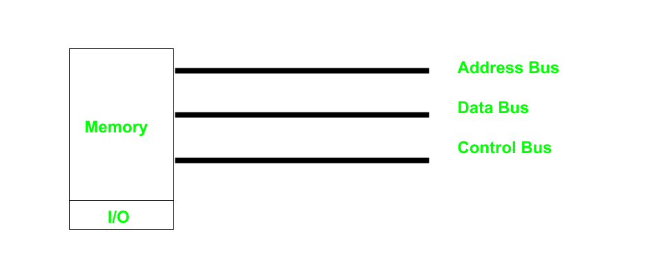
In memory-mapped I/O (MMIO), certain hardware devices are mapped into the system's memory address space. This means that the addresses used to access these devices are the same as those used for accessing regular memory locations.
Memory-mapped I/O involves mapping device registers to memory addresses. Accessing these devices is done by reading from or writing to specific memory locations.
- In it every bus in common due to which the same set of instructions work for memory and I/O. Hence we manipulate I/O same as memory and both have same address space, due to which addressing capability of memory become less because some part is occupied by the I/O.
Memory Addresses: The hardware registers of the device, which control its behavior and configuration, are assigned specific memory addresses.
Access: These registers can be read from or written to using standard memory access instructions, such as load (LDR) and store (STR) instructions on a CPU.
Note:
Memory-mapped I/O (MMIO) memory is not a part of the system memory. Instead, it refers to a range of addresses within the physical address space that are mapped to hardware registers of I/O devices. This mapping allows the CPU to access these hardware registers using memory access instructions, treating them as if they were ordinary memory locations.
- System memory, also known as RAM (Random Access Memory), is used by the CPU to store data and program instructions that are actively being processed. It is accessible using memory access instructions, and its contents can be read from and written to by the CPU.
- On the other hand, MMIO regions represent memory addresses that are mapped to hardware registers of I/O devices, such as graphics cards, network interfaces, or storage controllers. Accessing these addresses allows the CPU to control and communicate with these devices, but the data stored in MMIO regions is not stored in system memory.
Example:
In the context of VGA text mode, the address 0xB8000 (or 0xB800 for certain architectures) typically refers to the starting address of the memory-mapped I/O (MMIO) region used for displaying text on the screen.
When operating in VGA text mode, the CPU treats this address as if it were ordinary system memory. However, in reality, this address range is mapped to the video memory of the graphics card. Instead of accessing system RAM, the CPU accesses the video memory directly through MMIO to read from and write to the screen.
So, while the CPU perceives the memory address 0xB8000 as if it were part of the system's physical RAM, it actually corresponds to the video memory of the graphics card. Accessing this address allows the CPU to control what is displayed on the screen by interacting with the hardware registers of the VGA display adapter.
Advantages:
- Simplified Programming: MMIO simplifies programming by treating devices as if they were memory locations, allowing programmers to use familiar memory access techniques.
- Efficiency: MMIO can be more efficient than isolated I/O because it does not require special I/O instructions and can take advantage of the CPU's caching mechanisms.
- Faster I/O Operations: Memory-mapped I/O allows the CPU to access I/O devices at the same speed as it accesses memory. This means that I/O operations can be performed much faster compared to isolated I/O.
Disadvantages:
- Address Space Usage: MMIO consumes address space, potentially limiting the amount of memory available for other purposes.
- Lack of Protection: MMIO does not provide protection mechanisms to prevent unauthorized access to device registers.
2 Isolated I/O || Port-Mapped I/O (PMIO):
In isolated I/O, hardware devices are accessed using specialized input/output (I/O) instructions distinct from memory access instructions. These I/O instructions are specifically designed to communicate with hardware devices and are separate from the system's memory address space.
Port-mapped I/O (PMIO) uses special CPU instructions to communicate with hardware devices through I/O ports. This method is common for older and simpler devices. It uses separate addresses for ports in a separate address space. This address space is separate from the main memory address space and is accessed via the CPU's in and out instructions.
Since port addresses are distinct from memory addresses and the number of ports is not that large, the port address space is likely to be smaller than memory address space. For instance the Intel i8086 had 20-bit memory addresses (to address one megabytes of memory), but had port addresses only 16 bits wide.
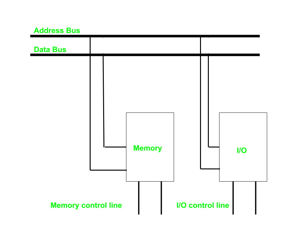
- In it we have common system bus (data and address) for I/O and memory but separate read and write control lines for I/O.
- When CPU decode instruction then if data is for I/O then it places the address on the address line and set I/O read or write control line on due to which data transfer occurs between CPU and I/O.
- As the address space of memory and I/O is isolated and the name is so. The address for I/O here is called ports. Here we have different read-write instruction for both I/O and memory.
Port Addresses: Hardware devices are assigned specific port addresses, separate from memory addresses, for input and output operations.
Access: Special I/O instructions, such as IN and OUT instructions on x86-based CPUs, are used to read from and write to device ports.
The I/O Address Space:
- Dedicated Space: The I/O address space is distinct from the system's RAM address space. In x86 architecture, this space is typically 16-bit, allowing for up to 65,536 (2^16) unique port addresses, ranging from 0x0000 to 0xFFFF.
- Access Mechanism: Ports are accessed using the in and out instructions, which perform read and write operations directly on these addresses.
- Interaction with I/O Ports: When a device is designed to work with port-mapped I/O, it is configured to respond to specific port addresses. The CPU communicates with these devices by sending and receiving data to/from these addresses. This communication is direct and does not involve the usual memory address translation mechanisms.
Reading from a Port:
When the CPU executes an in instruction, it specifies the port address and the register where the data should be stored. For example, reading a byte from port 0x60 (commonly used for the keyboard controller data port) looks like this:
mov dx, 0x60   ; Load the port address into DX
in al, dx      ; Read the byte from port 0x60 into AL
Writing to a Port:
Similarly, writing a byte to a port involves specifying the port address and the data to be written. For example, writing a byte to port 0x60:
mov dx, 0x60   ; Load the port address into DX
mov al, 0xFF   ; Load the data into AL
out dx, al     ; Write the byte in AL to port 0x60
Hardware and I/O Ports
- Device Registers: Each hardware device has registers mapped to specific I/O ports. These registers can be data registers, status registers, control registers, etc.
- Chipset Role: The system's chipset (part of the motherboard's architecture) helps manage these port addresses, ensuring that each hardware component responds to its designated port addresses.
Advantages:
- Address Space Conservation: Isolated I/O does not consume memory address space, allowing more memory to be available for other purposes.
- Protection: Isolated I/O provides a level of protection by restricting access to device ports, preventing unauthorized access by user-mode programs.
Disadvantages:
- Complexity: Isolated I/O may require additional instructions and programming techniques compared to MMIO, leading to increased complexity in software development.
- Performance Overhead: Isolated I/O instructions may have higher latency and overhead compared to memory access instructions, particularly on certain CPU architectures.
Example Hardware I/O Port Mappings
Here are some common I/O port mappings in x86 systems:
1 Keyboard Controller:
- Data Port:
0x60 - Command/Status Port:
0x64
2 Programmable Interrupt Controller (PIC):
- Master PIC Command:
0x20 - Master PIC Data:
0x21 - Slave PIC Command:
0xA0 - Slave PIC Data:
0xA1
3 Programmable Interval Timer (PIT):
- Channel 0 Data Port:
0x40 - Command Port:
0x43
4 Serial Ports:
- COM1: Base address
0x3F8 - COM2: Base address
0x2F8
3 Difference Between Memory Mapped I/O and Isolated I/O:
| Isolated I/O | Memory Mapped I/O |
|---|---|
| Memory and I/O have separate address space | Both have same address space |
| All address can be used by the memory | Due to addition of I/O addressable memory become less for memory |
| Separate instruction control read and write operation in I/O and Memory | Same instructions can control both I/O and Memory |
| In this I/O address are called ports. | Normal memory address are for both |
| More efficient due to separate buses | Lesser efficient |
| Larger in size due to more buses | Smaller in size |
| It is complex due to separate logic is used to control both. | Simpler logic is used as I/O is also treated as memory only. |
4 Usage:
MMIO:
- Commonly used for devices that require frequent and high-speed access, such as graphics cards, network interfaces, and storage controllers.
- Memory-mapped I/O is often used in graphics cards to provide fast access to frame buffers and control registers. The graphics data is mapped directly to memory, allowing the CPU to read from and write to the graphics card as if it were accessing regular memory.
- Network interface cards (NICs) often utilize memory-mapped I/O to transfer data between the network and the system memory. The NIC registers are mapped to specific memory addresses, enabling efficient data transfer and control over network operations.
Isolated I/O:
- Often used for legacy devices or specialized hardware where direct memory access is not feasible or practical.
- Isolated I/O is commonly used in embedded systems where strict isolation between the CPU and peripherals is necessary. This includes applications such as industrial control systems, robotics, and automotive electronics. Isolation ensures that any faults or malfunctions in peripheral devices do not affect the stability of the entire system.
- Microcontrollers often rely on isolated I/O to interface with various peripherals, such as sensors, actuators, and displays. Each peripheral is assigned a separate I/O port, allowing the microcontroller to control and communicate with multiple devices independently.
- Isolated I/O is preferred in real-time systems that require precise timing and deterministic behavior. By isolating the I/O operations, these systems can maintain strict control over the timing and synchronization of external events, ensuring reliable and predictable performance.

Join the discussion
Sign in with your account to post comments, reply to others, and participate in the conversation.
Login to Comment