
Disk Addressing
Disk addressing refers to the way in which data is located and accessed on a storage device. Disk addressing schemes are methods used to specify the location of data on a disk. In the early days of computing and within the context of real mode, the most common addressing scheme was Cylinder-Head-Sector (CHS). As technology evolved, Logical Block Addressing (LBA) emerged, providing a more straightforward and flexible method for addressing.
Types of Disk Addressing Schemes
- Cylinder-Head-Sector (CHS) Addressing
- Logical Block Addressing (LBA)
1 Cylinder-Head-Sector (CHS) Addressing
CHS addressing is a traditional method used to locate data on a disk. It utilizes three parameters:
- Cylinder: Identifies the track number on the disk.
- Head: Specifies the read/write head (or platter surface).
- Sector: Denotes the sector number within the track.
How CHS Addressing Works
In CHS addressing:
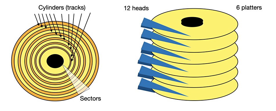
1 Cylinder (or Track)
It is the circular path on the surface of the disk platters.
- A cylinder is a collection of tracks that are at the same position on each platter in the disk stack.
- All the tracks that are at the same distance from the center are grouped into one cylinder.
- Tracks in the same cylinder are physically above or below each other on the disk platters.
- Imagine stacking multiple platters one above the other. Each platter has concentric tracks. All tracks that are vertically aligned form a cylinder. For example, the 10th track on the top platter and the 10th track on the bottom platter are part of the same cylinder.
Imagine a hard disk with multiple platters stacked vertically. Each platter is divided into concentric circles called tracks.
Disk Platter 1 (Top View)
+----------------------+
| Track 0              |
| Track 1              |
| Track 2              |
| Track 3              |
+----------------------+

Disk Platter 2
+----------------------+
| Track 0              |
| Track 1              |
| Track 2              |
| Track 3              |
+----------------------+


Tracks that are vertically aligned across all platters form a cylinder. For instance, Track 2 on Platter 1, Track 2 on Platter 2, etc., all belong to Cylinder 2.


Side View (Cylinders)

Platter 1: Track 2
Platter 2: Track 2
2 Head
It refers to the read/write head that accesses the data on a specific platter.
- A head is the mechanism that reads data from and writes data to the disk.
- Each platter in a hard disk has two surfaces (top and bottom).
- The head is positioned over a track to read or write data.
- Each platter surface has a dedicated read/write head. For a disk with two platters, there are typically four heads (two surfaces per platter).
Each side of a platter has a read/write head. In our example with two platters, we would have four heads: Head 0 and Head 1 for Platter 1, Head 2 and Head 3 for Platter 2.
Heads:

Platter 1: Head 0 (Top), Head 1 (Bottom)
Platter 2: Head 2 (Top), Head 3 (Bottom)
3 Sector
- It is the smallest unit of data storage on a disk, usually 512 bytes.
Let's assume each track has 8 sectors for simplicity.

		Sector 3
	Sector 2    Sector 4
Sector 1		  Sector 5
   Sector 8		Sector 6
		Sector 7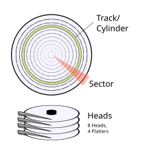
Addressing with CHS:
- Cylinder Number (C):
- Specifies the cylinder on the disk.
- Cylinders are numbered starting from 0.
- Head Number (H):
- Specifies the platter surface (head) from which data is read or written.
- Heads are numbered starting from 0.
- Sector Number (S):
- Specifies the sector within the stack.
- Sectors are numbered starting from 1.
Example
Let's say we want to read data from cylinder 2, Head 1, Sector 5:
- Cylinder (C) = 2
- This is the third track on all platters
- Head Number (H) = 1
- This refers to the read/write head for the bottom side of the platter 1.
- Sector Number (S) = 5
- This is the fifth segment on Track 2 of Platter 1, Bottom side.
This would be represented as CHS (0, 0, 1).
Data Storage Sequence In CHS Addressing:
In CHS (Cylinder-Head-Sector) addressing, the data storage sequence typically follows a pattern that optimizes read/write performance based on the mechanical structure of the disk. The sequence can vary based on the specific implementation, but a common pattern is to fill one cylinder completely across all heads before moving to the next cylinder.
Typical Data Storage Sequence
Filling a Cylinder:
- Start with the first cylinder (Cylinder 0).
- For each cylinder, iterate through all heads.
- For each head, iterate through all sectors.
Proceed to the Next Cylinder:
- Once all sectors in all heads of a cylinder are filled, move to the next cylinder.
For Example:
Let's assume a disk with the following specifications:
- Cylinders: 2
- Heads: 2 (Head 0 for top surface, Head 1 for bottom surface)
- Sectors per Track: 8
The storage sequence would look like this:
Cylinder 0:
- Head 0:
- Sector 1
- Sector 2
- Sector 3
- Sector 4
- Sector 5
- Sector 6
- Sector 7
- Sector 8
- Head 1:
- Sector 1
- Sector 2
- Sector 3
- Sector 4
- Sector 5
- Sector 6
- Sector 7
- Sector 8
Cylinder 1:
- Head 0:
- Sector 1
- Sector 2
- Sector 3
- Sector 4
- Sector 5
- Sector 6
- Sector 7
- Sector 8
- Head 1:
- Sector 1
- Sector 2
- Sector 3
- Sector 4
- Sector 5
- Sector 6
- Sector 7
- Sector 8
Cylinder 0:
  Head 0:
    Sector 1  -> Block 1
    Sector 2  -> Block 2
    Sector 3  -> Block 3
    Sector 4  -> Block 4
    Sector 5  -> Block 5
    Sector 6  -> Block 6
    Sector 7  -> Block 7
    Sector 8  -> Block 8
  Head 1:
    Sector 1  -> Block 9
    Sector 2  -> Block 10
    Sector 3  -> Block 11
    Sector 4  -> Block 12
    Sector 5  -> Block 13
    Sector 6  -> Block 14
    Sector 7  -> Block 15
    Sector 8  -> Block 16

Cylinder 1:
  Head 0:
    Sector 1  -> Block 17
    Sector 2  -> Block 18
    Sector 3  -> Block 19
    Sector 4  -> Block 20
    Sector 5  -> Block 21
    Sector 6  -> Block 22
    Sector 7  -> Block 23
    Sector 8  -> Block 24
  Head 1:
    Sector 1  -> Block 25
    Sector 2  -> Block 26
    Sector 3  -> Block 27
    Sector 4  -> Block 28
    Sector 5  -> Block 29
    Sector 6  -> Block 30
    Sector 7  -> Block 31
    Sector 8  -> Block 32
2 LBA (Logical Block Addressing)
Logical Block Addressing (LBA) is a method of specifying the location of blocks of data stored on computer storage devices such as hard drives and solid-state drives (SSDs). Unlike the older Cylinder-Head-Sector (CHS) addressing scheme, LBA abstracts the physical layout of the disk and uses a simple, linear addressing system.
Why LBA Was Introduced
The CHS addressing scheme faced significant limitations, particularly with the increasing storage capacities of modern disks. As hard drives grew larger, the constraints of CHS (limited number of cylinders, heads, and sectors) became a bottleneck. LBA was introduced to overcome these limitations and simplify the process of addressing large amounts of data.
How LBA Works
Linear Addressing:
- LBA uses a single number to address each sector on the disk. This number starts at 0 and increments by 1 for each subsequent sector, regardless of the physical geometry of the disk.
- For example, if a disk has 1,000,000 sectors, the sectors would be addressed from 0 to 999,999.
Sector Addressing:
- Each sector on the disk has a unique LBA. This linear addressing simplifies the process of locating data since the disk controller translates these addresses into physical locations internally.
- The operating system and applications see the disk as a contiguous array of sectors.
Translation by Disk Controller:
- The disk controller handles the translation between LBA and the actual physical location on the disk (the specific cylinder, head, and sector).
- Modern disk controllers use complex algorithms to optimize this translation process, often taking into account factors like seek times and rotational latency to improve performance.
Benefits of LBA
1 Simplified Addressing:
- LBA abstracts the complexity of the physical geometry of the disk, making it easier for operating systems and software to manage data storage.
2 Greater Storage Capacity:
- LBA removes the limitations imposed by CHS addressing, allowing for much larger storage capacities. Modern LBA can address up to 2^48 sectors, significantly exceeding the capacity limits of CHS.
3 Compatibility with Modern Storage:
- LBA is compatible with various types of storage media, including hard drives, SSDs, and optical drives, making it a versatile addressing scheme.
Conversion From CHS to LBA:
Formula:
LBA = (Cylinder * Heads per Cylinder + Head) * Sector per Track + (Sector - 1)
- Cylinder: The cylinder number (0-based).
- Head: The head number (0-based).
- Sector: The sector number (1-based).
- Heads per Cylinder: The total number of heads or surfaces per cylinder.
- Sectors per Track: The total number of sectors per track.
Example 1:
Let's assume we have a disk with the following specifications:
- Sectors per Track: 63
- Tracks per Cylinder: 255
- Cylinders: 1024
To calculate the LBA for a given CHS address (Cylinder 1, Head 1, Sector 1):
LBA = (1 x 255 + 1) x 63 + (1 - 1)
LBA = (256) x 63 + 0
LBA = 16128
So, the LBA corresponding to Cylinder 1, Head 1, Sector 1 is 16128.
Example 2:
Let's consider an example where we have the following CHS values:
- Cylinder: 10
- Head: 4
- Sector: 20
- Heads per Cylinder: 16
- Sectors per Track: 63
LBA=(10×16+4)×63+(20−1)
LBA = (160 + 4)×63 + 19
LBA = (160+4)×63+19
LBA = 164 × 63 + 19
LBA = 164 × 63 + 19
LBA = 10332 + 19
LBA = 10332 + 19
LBA = 10351
LBA = 10351

So, the LBA corresponding to CHS (10, 4, 20) is 10351.
Leave a comment
Your email address will not be published. Required fields are marked *