
Interrupts are a fundamental mechanism used by the x86 architecture to handle asynchronous events such as hardware signals, software requests, and exceptional conditions. They allow the CPU to respond to external and internal events in a timely manner, enabling multitasking, efficient I/O operations, and error handling
❔ What are Interrupts?
An interrupt is a signal (event) sent by a hardware device or a software instruction that temporarily halts the CPU's current activities and transfers control to a special piece of code known as an interrupt handler. Interrupts are used to handle events that require immediate attention, such as I/O operations, timer events, and hardware errors.
An interrupt is like a function call to the operating system, but it's initiated by hardware or software rather than by the program itself. When an interrupt occurs, the CPU transfers control to a specific interrupt handler, which is a piece of code responsible for handling the interrupt. This handler can then perform any necessary actions, such as servicing an I/O request or responding to a hardware event.
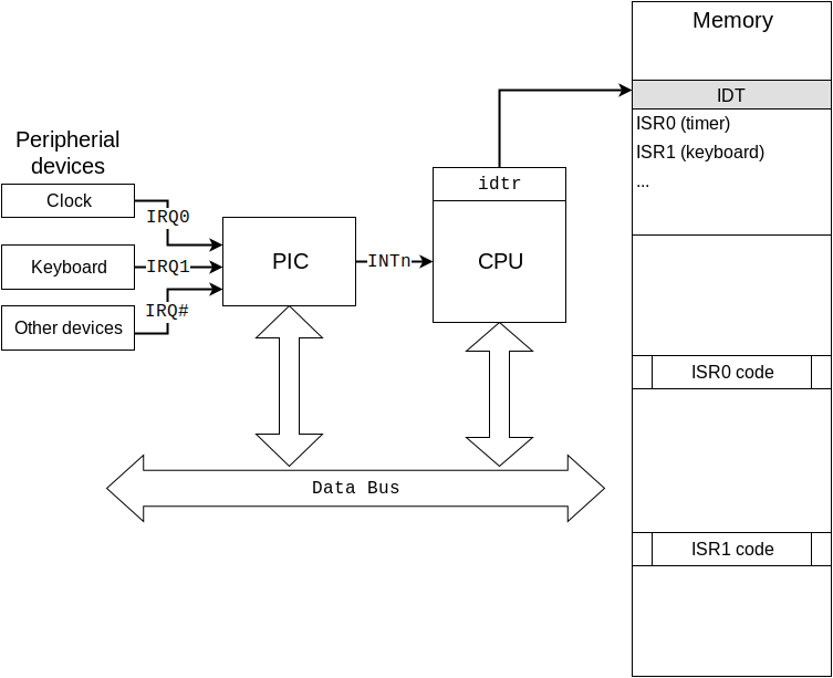
An interrupt is an event raised by software or hardware when it needs the CPU's attention. For example, we press a button on the keyboard and what do we expect next? What should the operating system and computer do after this? To simplify matters, assume that each peripheral device has an interrupt line to the CPU. A device can use it to signal an interrupt to the CPU. However, interrupts are not signaled directly to the CPU. In the old machines there was a PIC (Programmable Interrupt Controller) which is a chip responsible for sequentially processing multiple interrupt requests from multiple devices. In the new machines there is an Advanced Programmable Interrupt Controller commonly known as - APIC.
Types of Interrupts
There are several types of interrupts, including:
1️⃣ Hardware Interrupts:
These interrupts are generated by hardware devices such as keyboards, mice, disks, and network interfaces to signal events that require the CPU's attention. These interrupts are asynchronous and can occur at any time.
Hardware interrupts are further divided into:
- Maskable Interrupts: These interrupts can be disabled or enabled by the CPU. Examples include I/O interrupts, timer interrupts, keyboard and mouse interrupts.
- These can be enabled or disabled by the CPU using the interrupt flag (IF).
- They are used for general hardware events.
- Non-maskable Interrupts (NMI): These interrupts cannot be disabled by the CPU and are typically used for critical system events such as hardware errors (e.g., power failure, memory parity errors).
- These cannot be disabled.
- Used for critical events such as hardware failures.
Examples of Hardware Interrupts:
- Keyboard Interrupt: Generated when a key is pressed or released.
- Mouse Interrupt: Generated when the mouse is moved or a button is clicked.
- Timer Interrupt: Generated at regular intervals by the system timer to keep track of time.
- Disk Interrupt: Generated when a disk operation (read/write) is completed.
2️⃣ Software Interrupts:
These interrupts are generated by software instructions and are used to request specific services from the operating system. Software interrupts are often used for system calls and other privileged operations. Generated using int instruction.
- Exceptions: Automatically triggered by the CPU in response to specific conditions like division by zero, page faults, and invalid opcode. These occur in response to error conditions during program execution.
- Software-Generated Interrupts (System Calls): Triggered by the
intinstruction, allowing programs to request services from the operating system, such as I/O operations, memory allocation or process management.
Examples:
- INT Instruction in x86 Assembly: Used to invoke software interrupts. For example,
INT 0x80in Linux is used for system calls. - Traps: Generated by the CPU to handle specific conditions like divide-by-zero errors or invalid memory access.
⚡ Source of Interrupts:
- Hardware Interrupts: Comes from hardware devices like keyboard, timer.
- Software Interrupts: Generated by the software
intinstruction. - Exceptions: Generated by CPU itself in response to some error like
divide by zeroorpage fault.
⚡ Interrupts in Real Mode:
When an interrupt occurs the actual code that is invoked is called the Interrupt Service Routine (ISR). Whatever kind of event occurs, the processor uses one of several methods to transfer control to the ISR, allowing ISR to safely return control to whatever it interrupted after execution of ISR is over. At minimum, FLAGS and CS:IP are saved and the ISR'sCS:IP is loaded. This process is different for different implementation.
The Interrupt vector Table:
It is a data structure used in particularly x86 architecture. It contains the entries of interrupts. Each entry in the IVT contains 2 words of data: A value for the IP and a value for the CS.
- Fixed Location: The IVT starts at memory address 0x0000:0x0000, which is the physical address 0x00000.
- Entry Size: Each entry in the IVT is 4 bytes long.
- Number of Entries: The IVT contains 256 entries, corresponding to the 256 possible interrupt vectors (0-255). Every IVT entry provides the address of the ISR that should handle the particular interrupt.
- Structure: Each entry consists of a 4-byte segment pointer that points to the ISR.
Layout of the IVT:
The IVT layout in memory can be visualized as follows:
Address       Content
0x0000:0x0000 Vector 0: Offset 0, Segment 0
0x0000:0x0004 Vector 1: Offset 1, Segment 1
...
0x0000:0x03FC Vector 255: Offset 255, Segment 255
For example, let's say that we have the following interrupt:
int 10h		; 10h is the interrupt vector
			; processor uses it as an index
			; in the IVT
When we trigger the interrupt, the processor goes to the location 17 (10h = 16 in decimal, and since it starts from 0 which is 0-based indices, so 17th offset in IVT) location in IVT. Since each table entry is 4 bytes (2 bytes IP, 2 bytes CS), the processor goes to location (4*10h = 40h). At location 40h is the new IP value and at location 42h the new CS value. Every entry in IVT contains the ISR, that should handle the particular interrupt.
When the processor finds the particular ISR of the fired interrupt, it saved the current state of all register onto the stack, and transfers control to the ISR by loading the segment and offset from the IVT entry. After handling the interrupt like what that particular interrupt requesting. ISR return the control to the interrupted program, for the ISR uses iret instruction which restores the CS:IP and Flags which are pushed into the stack when interrupt occurred.
; For

int 0x02

The int 0x02 interrupt in the Interrupt Vector Table (IVT) maps to the third entry (index 2) in the IVT. This is because interrupt vectors are zero-indexed, meaning that int 0x00 maps to the first entry, int 0x01 maps to the second entry, and int 0x02 maps to the third entry.
Structure of an IVT Entry:
Each IVT entry is 4 bytes, consisting of a 2-byte offset (IP) and a 2-byte segment (CS).
- Offset (2 bytes): The offset within the segment where the ISR is located.
- Segment (2 bytes): The segment selector that points to the segment containing the ISR.
How Interrupts Work in Real Mode:
In real mode, the handling of interrupts involves several key steps and components, including the Interrupt Vector Table (IVT), interrupt service routines (ISRs), and the CPU's interrupt mechanism. Here’s a detailed explanation of how interrupts work in real mode:
Components Involved:
1️⃣ Interrupt Vector Table (IVT):
- Located at the fixed memory address 0x0000:0x0000 (physical address 0x00000).
- Contains 256 entries, each 4 bytes long, with segment pointers to ISRs.
2️⃣ Interrupt Service Routine (ISR):
- A function or code block that handles the interrupt.
- Each ISR is located at a specific segment in memory.
3️⃣ CPU:
- Executes instructions and manages interrupts through its interrupt handling mechanism.
Steps in Handling an Interrupt:
1️⃣ Interrupt Request:
- An interrupt request (IRQ) is generated by hardware devices or software.
- Hardware interrupts come from devices like the keyboard, mouse, or timer.
- Software interrupts are generated by instructions like
INTin assembly.
2️⃣ CPU Interrupt Acknowledgment:
- The CPU acknowledges the interrupt and determines its type.
- It identifies the interrupt vector number associated with the interrupt.
3️⃣ Finding the ISR:
- The CPU uses the interrupt vector number to index into the IVT.
- The IVT entry provides the segment address of the ISR.
4️⃣ Saving the CPU State:
- The CPU automatically pushes the current FLAGS register, CS (Code Segment), and IP (Instruction Pointer) onto the stack.
- This saves the state of the program so it can be resumed after handling the interrupt.
5️⃣ Disabling Further Interrupts:
- For most hardware interrupts, the CPU disables further interrupts to prevent nested interrupts.
- This is typically done by clearing the interrupt flag (IF) in the FLAGS register.
6️⃣ Executing the ISR:
- The CPU loads the CS and IP from the IVT entry and jumps to the ISR.
- The ISR executes and handles the specific interrupt (e.g., reading data from a keyboard).
7️⃣ Restoring the CPU State:
- After the ISR completes, it executes the
IRET(Interrupt Return) instruction. - The
IRETinstruction restores the saved FLAGS, CS, and IP registers from the stack. - This returns control to the point in the program where the interrupt occurred.
8️⃣ Re-enabling Interrupts:
- The
IRETinstruction or the ISR itself may re-enable interrupts by setting the interrupt flag (IF) if they were previously disabled.
When an interrupt occurs, the CPU performs the following steps:
1 Save the Current State: The CPU saves the current state of the program by pushing the values of the program counter (PC), flags register, and other relevant registers onto the stack.
2 Lookup the Interrupt Handler: The CPU looks up the address of the interrupt handler in the Interrupt Descriptor Table (IDT), which contains a list of interrupt vectors and their corresponding handler addresses.
3 Transfer Control to the Interrupt Handler: The CPU transfers control to the interrupt handler by setting the program counter (PC) to the address of the interrupt handler.
4 Execute the Interrupt Handler: The interrupt handler executes, performing whatever actions are necessary to handle the interrupt.
5 Restore the Previous State: After the interrupt handler completes execution, the CPU restores the previous state of the program by popping the saved values from the stack.
6 Resume Execution: The CPU resumes execution of the interrupted program.
⚡ Interrupt Descriptor Table (IDT)
The IVT we are discussing above is only available in real mode. In Protected Mode or Long Mode we can't use the IVT. Similar to IVT, IDT contains the entries which points to the ISR routine.
The Interrupt Descriptor Table (IDT) is a data structure in the IA-32 and x86-64 architectures, used to manage interrupts and exceptions. It is essential for the CPU to know where to find the Interrupt Service Routine (ISRs) for various interrupt. The IDT is used in Protected and Long Mode, while Real Mode uses the Interrupt Vector Table (IVT). It is the counterpart of the real mode IVT.
The Interrupt Descriptor Table (IDT) is a data structure used by the x86 architecture to implement an interrupt vector table. The IDT is used by the processor to determine the correct response to interrupts and exceptions.
It is quite similar to Global Descriptor Table (GDT) in structure. It depends on the GDT, so before setting up the IDT, ensure you have a working GDT. The GDT provides segment definitions that the CPU uses to access memory. A minimal GDT typically includes at least the null descriptor and the code and data segment descriptors.
Purpose: The IDT tells the CPU where the ISRs are located.
Structure:
- It consists of 256 entries, each corresponding to an interrupt vector.
- Each entry is 8 bytes long.
- Each entry describes the address and properties of an ISR.
Entries: Each entry is called a gate and can be an Interrupt Gate, Task Gate, or Trap Gate.
Types of Gates:
- Interrupt Gate:
- Clears the interrupt flag (IF) to disable further interrupts.
Used for most hardware interrupts.
- Clears the interrupt flag (IF) to disable further interrupts.
- Trap Gate:
- Does not clear the interrupt flag.
- Used for exceptions and debugging purposes.
- Task Gate:
- Switches the CPU to a different task by loading a new Task State Segment (TSS).
- Rarely used in modern systems.
IDTR
The location of the IDT is stored in the IDT Register (IDTR), which is loaded using the LIDT (Load IDT) instruction.
Structure: The IDTR is a 48-bit register in 32-bit mode & 80-bit in 64-bit mode:
- The first 16 bits contain the size (or limit) of the IDT in bytes minus one.
- The remaining 32 bits (in 32-bit mode) or 64 bits (in 64-bit mode) contain the base address of the IDT.
+-------------------------+
|  Limit (Size - 1)       |  (16 bits)
+-------------------------+
|  Base Address           |  (32 bits in 32-bit mode, | 64 bits in 64-bit mode) |
+-------------------------+

Limit: Specifies the size of the IDT in bytes minus one.
Base Address: The starting address of the IDT.

Note that the amount of data loaded by LIDT differs in 32-bit and 64-bit modes, Offset is 4 bytes long in 32-bit mode and 8 bytes long in 64-bit mode.
Imagine we have an IDT with 256 entries, and each entry points to an ISR. The IDTR will provide the CPU with the location and size of this IDT.
+---------------------------+---------------------------+---------------------------+---------------------------+  ...
| IDT Entry 0               | IDT Entry 1               | IDT Entry 2               | IDT Entry 3               |
+---------------------------+---------------------------+---------------------------+---------------------------+  ...
| Offset (15..0)            | Offset (15..0)            | Offset (15..0)            | Offset (15..0)            |
| Segment Selector          | Segment Selector          | Segment Selector          | Segment Selector          |
| Reserved (0)              | Reserved (0)              | Reserved (0)              | Reserved (0)              |
| Type (Gate Type)          | Type (Gate Type)          | Type (Gate Type)          | Type (Gate Type)          |
| DPL (Descriptor Privilege | DPL (Descriptor Privilege | DPL (Descriptor Privilege | DPL (Descriptor Privilege |
| Level)                    | Level)                    | Level)                    | Level)                    |
| Present (P)               | Present (P)               | Present (P)               | Present (P)               |
| Offset (31..16)           | Offset (31..16)           | Offset (31..16)           | Offset (31..16)           |
+---------------------------+---------------------------+---------------------------+---------------------------+  ...
Let's assume our IDT starts at memory address 0x00007E00 and has 256 entries.
- Limit: Since each entry is 8 bytes and we have 256 entries, the size is
256 * 8 = 2048bytes. Therefore, the limit is2048 - 1 = 2047(0x07FF). - Base Address: The base address of the IDT is
0x00007E00. - So, the IDTR will be loaded with:
- Limit:
0x07FF - Base Address:
0x00007E00
- Limit:
section .data
idt_start:
times 256 dq 0  ; Reserve space for 256 IDT entries

idt_end:

idt_descriptor:
    dw idt_end - idt_start - 1  ; Limit
    dd idt_start               ; Base Address

section .text
global load_idt
load_idt:
    ; Load the IDT descriptor into the IDTR
    lidt [idt_descriptor]
    ret
IDT Entry
- Each entry in the IDT is called a gate | Interrupt Descriptor.
- The IDT consists of 256 interrupt vectors or gates.
- The first 32 (0-31) entries are used for processor exceptions.
On 32-bit processor, the entries in the IDT are 8 bytes long.
The IDT is an array of 8-byte entries, each describing an interrupt or exception handler. Each entry in the IDT contains the following fields:
- Offset: The offset field contains the address of the interrupt handler.
- Selector: The selector field contains the segment selector for the interrupt handler.
- Type: The type field contains flags that specify the type of interrupt or exception and the privilege level at which the interrupt handler should run.
| Offset | Size | Name | Description |
| 0 | 2 bytes | Offset (low) | Low 2 bytes of interrupt handler offset |
| 2 | 2 bytes | Selector | A code segment selector in the GDT |
| 4 | 1 byte | Zero | Zero - unused |
| 5 | 1 byte | Type/attributes | Type and attributes of the descriptor |
| 6 | 2 bytes | Offset (high) | High 2 bytes of interrupt handler offset |
Noticed, A descriptor includes a selector from the GDT, so the IDT depends on the GDT. In the GDT, we must define a code segment (which we did in previous chapters) where the interrupt handlers will be stored. The interrupt descriptor then includes an offset to where the handler code begins.
The descriptor also defines an type/attribute byte with a number of flags:
| Bits | Code | Description |
| 0…3 | Gate type | IDT gate type |
| 4 | Storage Segment | Must be set to 0 for interrupt gates. |
| 5..6 | Descriptor privilege level | Gate call protection. This defines the minimum privilege level the calling code must have. This way, user code may not be able to call some interrupts. |
| 7 | Present | For unused interrupts, this is set to 0. Normally, it's 1. |
Interrupt Service Routines (ISR)
An Interrupt Service Routine (ISR) is a special type of subroutine or function in computer programming that is invoked when an interrupt occurs. ISRs are fundamental to interrupt-driven programming and are used to handle various types of interrupts, such as hardware interrupts, software interrupts, and exceptions.
Key Characteristics of ISRs
- Invocation: ISRs are automatically invoked by the processor when an interrupt occurs. The execution of the current program is temporarily halted, and control is transferred to the ISR to handle the interrupt.
- Handling Interrupts: ISRs handle a wide range of interrupts, including hardware interrupts generated by peripheral devices (e.g., keyboard, mouse, timer), software interrupts triggered by software instructions (e.g., system calls), and exceptions (e.g., divide by zero, page faults).
- Priority: ISRs are executed with a certain priority based on the type of interrupt being handled and the system configuration. Higher-priority interrupts can preempt lower-priority interrupts, depending on the interrupt controller's settings.
- Context Switching: ISRs execute in a special context known as the interrupt context. They must be designed to execute quickly and efficiently since they temporarily suspend the execution of the interrupted program.
⚡ Programmable Interrupt Controller (PIC)
A Programmable Interrupt Controller (PIC) is a interrupt controller that manages interrupt signals received from devices by combining multiple interrupts into a single interrupt output. PIC is found on most PCs today. The most common PIC in older x86 systems is the Intel 8259A, often used in pairs to provide 15 usable IRQ lines.
The PIC manages interrupt requests from peripheral devices, prioritizes them, and sends them to the CPU.
Interrupt Lines: Each PIC can handle 8 IRQ lines. When cascaded, typically with a master and a slave PIC, they can handle 15 IRQ lines (IRQ0-IRQ15).
Interrupt Vector Table (IVT):
In real mode, the x86 CPU uses the IVT, which is a table of pointers to interrupt handlers (ISR) located at the beginning of memory (address 0x0000 to 0x03FF). Each entry is 4 bytes (2 bytes for the segment, 2 bytes for the offset).
- In real mode, there is an IVT (Interrupt Vector Table) which is located at the fixed address
0x0000
Basic Operation:
- Interrupt Request (IRQ): A device sends an interrupt signal to the PIC on one of its IRQ lines.
- IRR Update: The PIC sets the corresponding bit in the IRR.
- Priority Resolution: The PIC determines if the interrupt should be sent to the CPU based on its priority and the current state of the IMR.
- ISR Update: If the interrupt is allowed, the PIC sets the corresponding bit in the ISR and sends an interrupt to the CPU.
- Interrupt Handling: The CPU acknowledges the interrupt and executes the corresponding ISR.
- End of Interrupt (EOI): After handling the interrupt, the ISR sends an EOI command to the PIC to clear the ISR bit.
IRQ (Interrupt Request):
An Interrupt Request (IRQ) is a signal sent to the processor from hardware or software indicating an event that needs immediate attention.
IRQs allow a computer system to manage multiple devices and processes efficiently by handling events asynchronously. For example, instead of the CPU constantly polling a device to check if it needs attention (which is inefficient), the device sends an IRQ to the CPU only when it requires service.
In x86 systems, IRQ are managed by the PIC. The 8259A PIC, commonly used in older systems, can handle up to 15 IRQ lines. Modern systems use the Advanced Programmable Interrupt Controller (APIC) for more complex interrupt handling.
| IRQ Line | Interrupt Vector | Description |
|---|---|---|
| IRQ0 | 32 | System timer |
| IRQ1 | 33 | Keyboard |
| IRQ2 | 34 | Cascade for IRQs 8–15 |
| IRQ3 | 35 | Serial port 2 |
| IRQ4 | 36 | Serial port 1 |
| IRQ5 | 37 | Parallel port 2 |
| IRQ6 | 38 | Floppy disk controller |
| IRQ7 | 39 | Parallel port 1 |
| IRQ8 | 40 | Real-time clock |
| IRQ9 | 41 | Free for peripherals (redirected) |
| IRQ10 | 42 | Free for peripherals |
| IRQ11 | 43 | Free for peripherals |
| IRQ12 | 44 | PS/2 mouse |
| IRQ13 | 45 | FPU/coprocessor/inter-processor |
| IRQ14 | 46 | Primary ATA hard disk |
| IRQ15 | 47 | Secondary ATA hard disk |
IRQ Handling Process:
- Interrupt Generation: A hardware device or software generates an interrupt signal.
- Interrupt Controller: The Programmable Interrupt Controller (PIC) receives the interrupt signal and prioritizes it among other pending interrupts.
- CPU Notification: The PIC sends an interrupt signal to the CPU.
- Interrupt Vector Table (IVT): The CPU looks up the interrupt vector table to find the address of the ISR.
- ISR Execution: The CPU executes the ISR to handle the interrupt.
- End of Interrupt (EOI): The ISR signals the PIC that the interrupt has been handled by sending an EOI command.
Programming the 8259A PIC:
Initializing the PIC:
Configuring the Programmable Interrupt Controller (PIC) is a crucial step in setting up hardware interrupts in x86 systems. The PIC allows for the mapping of hardware interrupt signals to CPU interrupt vectors, enabling the CPU to handle hardware events efficiently. The reasons for configuring the PIC include remapping interrupts to avoid conflicts with CPU interrupts, selecting which interrupts to receive, and setting up the correct operational mode for the PIC.
PIC must be configured to receive interrupt requests (IRQs) from devices and send them to CPU.
Why Configure the PIC?
- Remap the Interrupts: By default, the PIC uses interrupt vectors 0–15, which conflict with the CPU's reserved vectors (especially the first 32 vectors used for exceptions and other purposes). Thus, the PIC interrupts need to be remapped to another range.
- Select Which Interrupts to Receive: Typically, you don't need to handle all possible hardware interrupts. You can mask (disable) unwanted interrupts.
- Set Up the Correct Mode: The PIC must be configured to operate in the appropriate mode, such as 8086/88 mode.
PIC Initialization Process
The initialization of the PIC involves sending a series of Initialization Command Words (ICWs) to its command and data ports.
Ports Used by the PIC
- Master PIC (PIC1): Command port (0x20), Data port (0x21)
- Slave PIC (PIC2): Command port (0xA0), Data port (0xA1)
The PIC must be initialized before it can be used. This involves sending Initialization Command Word (ICWs) to the PIC's command and data ports.
- ICW1: Initialize the PIC and define operational parameters.
- ICW2: Define the base address for the interrupt vectors.
- ICW3: Setup cascading (only for master/slave configuration).
- ICW4: Define additional operational parameters.
Initialization Command Words (ICWs)
- ICW1: Begins the initialization sequence.
0x10: Start initialization.0x01: Require ICW4.
- ICW2: Sets the base interrupt vector address.
- ICW3: Configures the cascading (relationship between master and slave PICs).
- ICW4: Sets additional operational parameters, like 8086/88 mode.

Leave a comment
Your email address will not be published. Required fields are marked *