
To jump to protected mode, you need to set up the Global Descriptor Table (GDT) and load the segment registers with selectors pointing to entries in the GDT.
Protected Mode
It is an operational mode of x86-compatible CPU. In this mode, the CPU has access to all its features, including the ability to use virtual memory, access more than 1MB of memory, and use various levels of privilege.
- It is 32 bit mode (can access mem up to 4GB)
Key Features of Protected Mode:
- Memory Protection:
- In protected mode, memory can be protected so that one program cannot access the memory of another program.
- Multitasking:
- Protected mode allows multitasking by providing each program with its own memory space.
- Virtual Memory:
- Protected mode allows for the use of virtual memory, which means that a program can use more memory than is physically available.
- Privilege Levels:
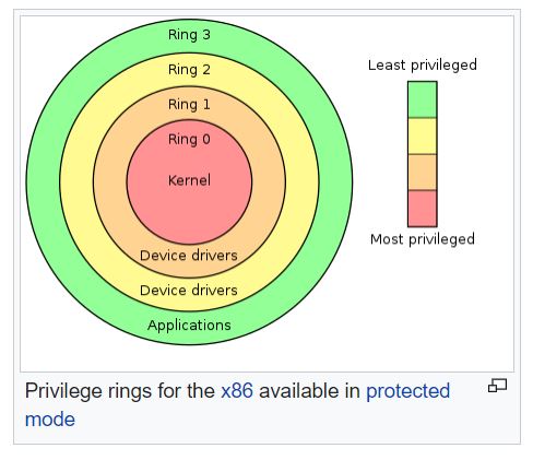
- Protected mode supports four privilege levels (called rings), 0 to 3.
- Ring 0 is the most privileged level and is used by the operating system kernel.
- Ring 3 is the least privileged level and is used by user applications.
- 32-bit Addressing:
- Protected mode supports 32-bit addressing, allowing access to up to 4 GB of memory.
Why Protected Mode:
- We can address 4GB of memory.
- Memory addresses are specified using a flat model, without segmentation.
- We can specify which memory areas a process can write to, and detect when it tries to write somewhere else (which is why the whole thing is called “protected mode”).
- Our kernel code can run with a higher privilege level than other processes, thus performing operations that ordinary processes should not be able to perform.
In real mode, all memory is shared between all processes running, and there is no memory protection. If a program accidentally overwrites a section of memory used by another program or the operating system kernel, it can cause the entire system to crash.
Protected mode, on the other hand, provides memory protection and multitasking capabilities:
1 Memory Protection:
- In protected mode, each process has its own memory space, and memory is protected so that one process cannot access the memory of another process.
- If a process tries to write to memory it isn't supposed to, the processor detects this and notifies the operating system kernel.
- The kernel can then terminate the misbehaving process, preventing it from causing harm to other processes or the operating system.
2 Multitasking:
- Protected mode allows multitasking by providing each process with its own memory space.
- This allows multiple processes to run simultaneously, each with its own memory space, without interfering with each other.
Protected mode, therefore, provides a more secure and stable environment for running multiple processes simultaneously, making it essential for modern operating systems.
Modern operating systems would not be possible without the ability of a CPU to execute code at different privilege levels. This feature became available for mainstream PCs in the early eighties, when Intel introduced its 80286 and 80386 CPUs, and was readily employed by operating systems like Windows 3.11 and, of course, Linux, which Linus Torvalds once called “a project to teach me about the 386”.
Protected mode is one of the key features that make modern operating systems like Windows, Linux, and macOS robust and reliable. It ensures that the system remains stable even when individual processes misbehave.
With these features, Intel has actually provided operating system developers with the hardware tools they need to write stable operating systems!
Memory Addressing in Protected Mode:
In protected mode, memory addressing is more flexible and complex compared to real mode. Protected mode offers a 32-bit flat memory model, allowing access to up to 4 GB of memory. Memory addressing in protected mode involves the following components:
Segmentation:
- Segmentation in protected mode is more flexible compared to real mode.
- Memory is divided into variable-sized segments defined by segment descriptors in the Global Descriptor Table (GDT) or the Local Descriptor Table (LDT).
- Each segment descriptor contains information such as base address, segment limit, access rights, and other attributes.
2. Flat Memory Model:
- Protected mode supports a flat memory model, where all memory is accessed through a single, continuous address space.
- In a flat memory model, segment registers typically hold a base address of 0 and a limit of 4 GB, allowing access to the entire address space.
3. Virtual Memory:
- Protected mode supports virtual memory, allowing each process to have its own virtual address space.
- Virtual memory is implemented using page tables, which map virtual addresses to physical addresses.
- Each process has its own set of page tables, allowing the operating system to allocate memory to processes dynamically.
Addressing Modes:
- In protected mode, 32-bit addressing is used, allowing access to up to 4 GB of memory.
- Memory addresses are typically represented as 32-bit linear addresses.
- Segment registers are still used to access different segments of memory, but in a flat memory model, they are often set to cover the entire address space.
Descriptor
A descriptor in the context of x86 architecture, specifically in the Global Descriptor Table (GDT), is a data structure that defines a segment of memory. Descriptors contain information about the base address, limit, access rights, and other attributes of the segment.
The GDT ("Global Descriptor Table") is a data structure used to define the different memory areas: the base address, the size and access privileges like execute and write. These memory areas are called "segments".
- CPU uses the GDT to describe its internal memory segmentation.
The first descriptor in the GDT is always a null descriptor and it can never be used to access memory. At least two segment descriptors along with the null descriptor are needed for the GDT, because the descriptor contains more information than just the base and limit fields.
Components of a Descriptor:
- Base Address:
- Specifies the starting address of the segment.
- It is 32 bit number. It is split into three parts.
- Limit:
- Specifies the size of the segment.
- Segment Limit (20 bits) = Size of a segment.
- Access Rights:
- Specifies the type of access allowed for the segment (e.g., read, write, execute).
- Specifies the privilege level required to access the segment (ring level).
- Type:
- Specifies the type of segment (code, data, system).
- Granularity:
- Specifies the granularity of the limit field (byte or 4 KB page).
- If
0: limit is specified in bytes. - If
1: limit is specified in 4k blocks.
Types of Descriptors:
- Code Segment Descriptor:
- Defines a segment containing executable code.
- Data Segment Descriptor:
- Defines a segment containing data.
- System Segment Descriptor:
- Defines system segments used by the operating system.
Format of a Descriptor:
A descriptor in the GDT has the following format:
| Start | End | Meaning | Size |
|---|---|---|---|
| 63 | 56 | Base (bits 24 - 31) | 8 bits |
| 55 | 52 | Flags | 4 bits |
| 51 | 48 | Limit (bits 16 - 19) | 4 bits |
| 47 | 40 | Access byte | 8 bits |
| 39 | 16 | Base (bits 0 - 23) | 24 bits |
| 15 | 0 | Limit (bits 0 - 15) | 16 bits |
From this table, one can see that it defines a 32 bit base which is a linear address of where the segment begins and a 20 bit limit which is the maximum addressable unit.
The access byte is 8 bits in flags that describe different access privileges. The byte breaks down like this:
| Bit | Code | Description |
|---|---|---|
| 7 | Pr | Present bit. Must be 1 for all selectors. |
| 6-5 | Privl | Privilege bits. Defines the ring level this selector is allowed to be used from. |
| 4 | Always 1 | |
| 3 | Ex | Executable bit. 1 for code, 0 for data |
| 2 | DC | Direction bit/Conforming bit. This is a direction bit for data selectors, in which case when it is set to 0, the segment grows up. 1, it’ll grow down. This is a conforming bit for code selectors. When is is set to 1, execution is allowed by the defined privilege level or below. When it’s 0, it’s only allowed from the defined privilege level. |
| 1 | RW | Readable for code selectors, Writeable for data selectors. Code selectors can’t have write access and data selectors don’t have read access. |
| 0 | Ac | Leave this as 0. The CPU will set it to 1 once the segment is accessed |
The flags nibble is 4 bits that control size:
| Bit | Code | Description |
|---|---|---|
| 7 | Gr | Granularity when set to 0 will make the limit be interpreted in bytes. When it’s set to 1, the limit is defined in pages (4KiB blocks) |
| 6 | Sz | Size when 0 defines 16-bit protected mode. 1 defines as 32-bit mode selectors |
| 5 | L | Long when set to 1 will setup 64-bit mode selectors. Sz must be set to 0 |
| 4 | Unused. Set to 0 |
|  63 - 56  |  55  |  54 - 52  |  51  |  50 - 48  |  47 - 16  |  15 - 0  |
| Base[31:24]| G(Granularity)| D/B | S | Type(11:8)| Limit[19:0]| Base[15:0]|
- Base[15:0]: Lower 16 bits of the base address.
- Base[31:24]: Upper 8 bits of the base address.
- Limit[19:0]: Lower 20 bits of the segment limit.
- Type(11:8): Segment type and access rights.
- S: Descriptor type (0 for system, 1 for code or data).
- D/B: Default operand size (0 for 16-bit, 1 for 32-bit).
- G: Granularity (0 for byte, 1 for 4 KB page).
Original value
00CF9A000000FFFF

base  24-31 : 00
flags       : C  (1100b)
limit 16-19 : F
access      : 9A (10011010b)
base 23-0   : 000000
limit 15-0  : FFFF
Example:
The following descriptor defines a code segment with base address 0, limit 4GB, and access rights allowing read and execute access for privilege level 0:
0x00cf9a000000ffff

This particular entry says it’s at a base of 0x00000000, has a limit of 0xFFFFF. The access byte tells us that the segment is:
	Present
	Is privileged to Ring-0
	Is executable
	Can ONLY be executed in Ring-0
	Is readable

The flags also tell us that the segment has:
	A limit that is expressed in 4KiB units
Our selectors are 32 bits- Base Address: 0x00000000
- Limit: 0xffff (4 GB)
- Access Rights: 0x00cf9a00
- G=1, D/B=1 (32-bit), S=1 (code/data), Type=0b1010 (executable, read-only), DPL=00 (privilege level 0)
This descriptor allows code execution from address 0 to 4 GB.
Different Memory Models
- Flat Memory Model
- Segmentation
- Paging
1 Flat Memory Model:
- The entire memory space is treated as a single, continuous address space.
- Segmentation is essentially disabled, and all memory segments start at physical address 0.
- It's commonly used in protected mode programming to simplify memory management.
2 Segmentation:
In the x86 architecture:
- Segmentation divides memory into segments of varying sizes, allowing different parts of memory to be accessed with different privileges.
- Each segment has a base address and a limit.
- Segment registers hold the base addresses of the current segment.
- Segmentation is commonly used in real mode and protected mode, but it's mainly disabled or used in a simplified form in 32-bit and 64-bit operating systems.
3 Paging:
Paging is a memory management scheme that allows the physical memory to be non-contiguous.
- Memory is divided into fixed-size blocks called pages.
- Virtual memory is divided into blocks of the same size called virtual pages.
- Pages are mapped to physical memory using page tables.
- Paging is used to implement virtual memory, allowing processes to use more memory than physically available.
Differences:
| Feature | Flat Model | Segmentation | Paging |
|---|---|---|---|
| Memory Model | Single continuous space | Divided into segments | Divided into pages |
| Addressing | Linear address | Segmented address | Virtual address |
| Address Translation | Direct | Segment base + Offset | Page table lookup |
| Memory Management | Simple | Complex | Complex |
| Protection | Limited | Limited | Enhanced |
| Usage | Protected mode | Real mode, Protected mode | Protected mode, Long mode |
Example:
Let's consider an example where we want to access memory address 0x12345678:
Flat Memory Model:
- Linear Address:
0x12345678 - Directly accesses physical memory.
Segmentation:
- Segment base:
0x10000 - Offset:
0x5678 - Physical address:
0x10000 + 0x5678 = 0x15678
Paging:
- Virtual address:
0x12345678 - Page table lookup determines the physical address corresponding to the virtual address.
Switching to Protected Mode:
To switch to protected mode, you need to perform the following steps:
- Set up the Global Descriptor Table (GDT):
- The GDT is a table that defines the memory segments used in protected mode.
- Load the GDT:
- The
lgdtinstruction is used to load the GDT.
- The
- Enable Protected Mode:
- Set the Protected Mode Enable (PE) bit in the Control Register 0 (CR0).
- Set up the Segment Registers:
- Set up the segment registers (CS, DS, SS, ES, FS, and GS) to point to the appropriate descriptors in the GDT.
- Jump to Protected Mode:
- Jump to the entry point in protected mode.
->1 Set up the GDT:
- Each entry in the GDT describes a segment of memory with attributes such as base address, limit, access permissions, and type.
- You'll typically define entries for code, data, stack, and possibly other segments.
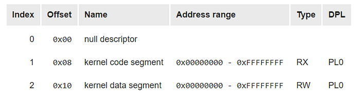
For our kernel, we only need three descriptors:
- A NULL-descriptor (an empty descriptor that is required to exist).
- A 4GB code descriptor.
- A 4GB data descriptor.
The Null Descriptor:
The Null Descriptor is simply 8 empty bytes.
The Code descriptor:
The code descriptor should be configured like this:
- Base address = 0x0
- Limit = 0xffff (with page granularity turned on, this is actually 4GB)
- Access byte
- Present = 1
- Privilege level = 0 (privilege level 0 is for kernel code)
- Executable = 1 (this is a code segment)
- Direction = 0
- Readable = 1 Combining all these bits gets us the value 1001 1010b, or 0x9a.
- Flags
- Granularity = 1 (for 4KB pages)
- Size = 1 (32-bit style) Combining all these bits gets us the value 1100 1111b, or 0xcf.
The Data descriptor:
The data descriptor should be configured like this:
- Base address = 0x0
- Limit = 0xffff (with page granularity turned on, this is actually 4GB)
- Access byte
- Present = 1
- Privilege level = 0 (privilege level 0 is for kernel code)
- Executable = 0 (this is a data segment)
- Conforming = 0
- Writable = 1 Combining all these bits get us the value 1001 0010b, or 0x92.
- Flags
- Granularity = 1 (for 4KB pages)
- Size = 1 (32-bit style) Combining all these bits get us the value 1100 1111b, or 0xcf.
; Define segment selectors
CODE_SEG equ 8
DATA_SEG equ 16

; Define GDT entries
gdt_start:
    NULL_SEL    equ $ - gdt_start
    db 0,0,0,0             ; Null segment
CODE_SEL    equ $ - gdt_start
    db 0xFF,0xFF,0,0       ; Code segment
    db 0,0,0,0
    db 0x9A,0xCF,0,0
DATA_SEL    equ $ - gdt_start
    db 0xFF,0xFF,0,0       ; Data segment
    db 0,0,0,0
    db 0x92,0xCF,0,0

gdt_end: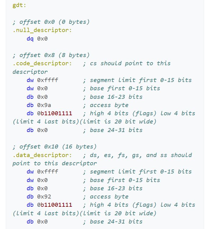
                      Pr  Priv  1   Ex  DC   RW   Ac
0x9A == 1001 1010  == 1   00    1   1   0    1    0
0x92 == 1001 0010  == 1   00    1   0   0    1    0

We have page-granularity and 32-bit mode
                      G   D   0   Av
0xCF == 1100 1111  == 1   1   0   0
Two things to point out here in this photo. First, the access bytes would have been more helpful to the reader if these were given in binary, rather than hexadecimal (‘0x9a’ and ‘0x92’). Secord, the assembler does not have something lower in amount of bits than ‘db’, which is 8-bit direct bits. If it did, it could help the reader better understand the separation that is actually going on within the ‘0b11001111’ and ‘0b11001111’, where we are forced to combine the flag bits with a portion of the limit bits.
I hope by reading this code you would agree the jumping and disorderly placement of bit meaning for these descriptors. However, this is probably due to the historical or general hardware ease of interpretation with the ending machine code after the assembler helps out.
We are establishing three different segments: null, kernel mode code, and kernel mode data. There is no user space in this or the task state segment (TSS), of which are common frameworks one would set up for a minimalistic OS. Mainly for the user code and user data the ring would be three instead of zero. For the TSS, the ring would be one. I digress. In this code snippet, the aim is to open up and access 4 GB, 0x0000000 to 0xFFFFFFFF. Therefore, the base address will be 0x00000000 and the limit will be (0xFFFFFFFF – 0x00000000) + 1, or 0xFFFFFFFF. You will see the use of the flags for this large of a limit.
The null descriptor segment is used by the CPU only and should not have any data in there. Since the null descriptor is 8 bytes, it could be used for the pointer to the GDT, which is 6 bytes. However, in this example all the bytes and bits are set to 0.
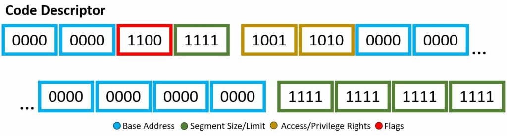
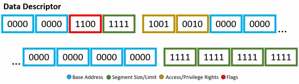
The 8 byte kernel mode code descriptor segment has the following:
- Base Address — b0000 0000 0000 0000 0000 0000 0000 0000
- Segment Size/Limit — b1111 1111 1111 1111 1111
- Access/Privilege Rights — b1001 1010
- Flags — b1100
To speak on the access rights of 0x9a or b1001 1010 in detail, let’s begin. The segment presence is set, therefore no exception shall be expected when referring this segment. The two-bit DPL is 00, therefore this code descriptor has ring-0 or highest privileges. Makes sense, you don’t want malicious programs or blissfully unaware users to take advantage of the kernel code descriptor. The DT is set, obvious, as this is indeed a descriptor. The type is given as set or announcing this is a code segment, meaning the use of C, W, and flag B. The conforming bit is not set, therefore this code segment can only be accessed by its own privilege ring and higher (however in this case, it is already the highest level of privilege). The writable bit is set, therefore write access is granted. Finally, the Access bit is not set, therefore it is currently in software’s hands. This final bit being not set is a little odd, generally you want to keep this not set and let the hardware have its turn. Oh well, this is Wikipedia code snippets… As for the flags, b1100, there is more to uncover. The granularity bit is set, therefore paging units are being utilized. The operand size is set, meaning because the type was set in the access bytes, we are granted to use the big opcode size, of which if set, which it is, the the maximum offset size for the data segment is 32-bit 0xFFFFFFFF. This is allowing us to be able to reach the actual desired limit. The long-mode flag is not set, therefore 64-bit rules will not be applied. Lastly, the AVL or wildcard flag is not set or being used.
The 8 byte kernel mode data descriptor segment has the following:
- Base Address — b0000 0000 0000 0000 0000 0000 0000 0000
- Segment Size/Limit — b1111 1111 1111 1111 1111
- Access/Privilege Rights — b1001 0010
- Flags — b1100
You might notice, wow this is very similar to the code segment descriptor — right you are. It seems whoever put this code snippet together wanted the only different between the two, well, very slim. Nevertheless, lets dive into it. The access bits of b1001 0010 will be our first subject. The segment presence bit is set, no exception will be given if this code segment is referenced. The DPL two-bits are set to 00, of which is ring-0, highest privilege. The DT is set, well yes, this is a descriptor! The type given is not set, therefore it is a stack/data segment type. The use of E, R, and D-flag will be applied. The Expanded-down or direction bit is not set, therefore augmentation will begin upward, in other words the offset will be greater than the limit. The readable bit is set, read access is enabled. Once again, the access is set to software, and still questionable, the reading in other resources state this should actually be left to 1 as the CPU/hardware will be accessing it. Now for the flag byte, b1100. The granularity bit is set, therefore units of paging will be utilized. We had type 0, therefore the default operand size will be used. This default operand size bit is set, meaning 32-bit segment rules. The long-mode flag is not set, no use of 64-bit rules and the wild card or AVL bit is not set meaning this is not used either.
From the code snippet, their comments show the offsets between the different descriptor segments is 8-bytes. This will be important and handy when using these in the actual initialization of the kernel file.
Similar code in C/C++:
// This structure contains the value of one GDT entry.
// We use the attribute 'packed' to tell GCC not to change
// any of the alignment in the structure.
struct gdt_entry_struct
{
    uint16_t limit_low;           // The lower 16 bits of the limit.
    uint16_t base_low;            // The lower 16 bits of the base.
    uint8_t  base_middle;         // The next 8 bits of the base.
    uint8_t  access;              // Access flags, determine what ring this segment can be used in.
    uint8_t  granularity;         // low 4 bits are high 4 bits of limit
    uint8_t  base_high;           // The last 8 bits of the base.
} __attribute__((packed));
typedef struct gdt_entry_struct gdt_entry_t;
Now we have this GDT descriptor, time to load the gdt.
-> Load the GDT:
We have define the global descriptor table in memory, containing the 3 entries of exactly 8 bytes each. Now how do we tell the processor about it?
This is easy to tell the processor because processor offers a single instruction to load the GDT:
lgdt [pointer to gdt entries structure]GDT_start: ; must be at the end of real mode code
GDT_null:
; Null segment descriptor
dd 0x0
dd 0x0
GDT_code:
; Code segment descriptor
dw 0xffff
dw 0x0
db 0x0
db 0b10011010
db 0b11001111
db 0x0
GDT_data:
; Data segment descriptor
dw 0xffff
dw 0x0
db 0x0
db 0b10010010
db 0b11001111
db 0x0
GDT_end:
GDT_descriptor:
    dw GDT_end - GDT_start - 1
    dd GDT_start
When you calculate the limit for the GDT descriptor, you need to subtract 1 from the total size of the GDT because the limit is specified in 4KB blocks. The -1 adjustment accounts for the fact that the limit is one less than the actual size of the GDT.
In x86 assembly language, the GDTR (Global Descriptor Table Register) is a special register that holds the base address and limit of the Global Descriptor Table (GDT). To load the GDT, you need to load its base address and limit into the GDTR using the lgdt instruction.
Now to load the table with the lgdt instruction, we’ll need yet another structure: the pointer to the global descriptor table. This takes the following form:
| Field | Size | Description |
| Size | 2 bytes | Number of bytes (not entries) in the global descriptor table, minus one |
| Offset | 4 bytes | Linear address of global descriptor table |
There’s a fancy reason why the table size is actually its number of bytes minus one. The system designers decided that the maximum number of bytes in the table should be 65,536 (2^16), but two bytes can only hold values between 0 and 65,535. So you actually put in one less than the total, so that 0 means 1, 1 means 2, and so on. A consequence of this that it’s not possible to have a global descriptor table with zero entries in it.
GDT_descriptor:
dw GDT_end - GDT_start - 1
dd GDT_startgdt [GDT_descriptor]We have now informed the processor of the existence of our global descriptor table, and are one step closer to switching to protected code. It didn’t require a lot of complicated code – all we’ve done is created a set of values and used lgdt to tell the processor where it is.

Leave a comment
Your email address will not be published. Required fields are marked *