
In the context of x86 real mode, the memory map is defined by the original IBM PC architecture and includes several well-defined regions.
The real mode memory map of x86 system describes the organization and allocation of memory within the first 1 MB of addressable space. Understanding this memory map is crucial for low-level programming tasks. Real mode is the mode the CPU operates in immediately after a system reset, allowing only 20-bit memory addressing and access to a maximum of 1 MB of memory.
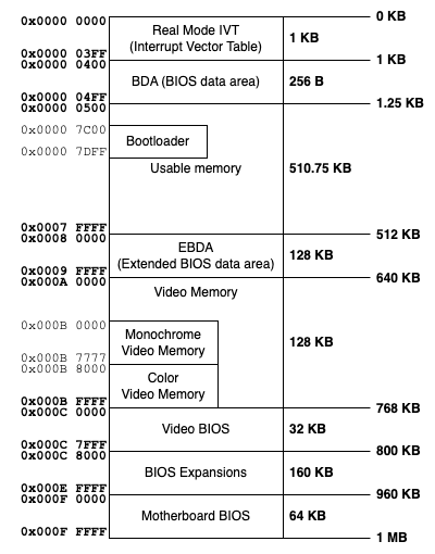
Here's an overview of the memory map in real mode:
Real Mode Memory Map
🤷♂️ Explanation:
1 Interrupt Vector Table (IVT):
- Addresses:
0x00000to0x003FF - Size: 1 KB (256 entries, 4 bytes each)
- Description: This table holds pointers to interrupt service routines (ISRs). Each entry is 4 bytes, consisting of a 2-byte segment and a 2-byte offset.
- Usage: The CPU consults the IVT when an interrupt occurs to determine the ISR's location.
2 BIOS Data Area (BDA)
- Addresses:
0x00400to0x004FF - Size: 256 bytes
- Description: This area contains system data used by the BIOS such as hardware configuration and status information.
- Equipment list (e.g., number of drives).
- COM and LPT port addresses.
- Keyboard status.
3 Low Conventional Memory:
- Addresses:
0x00500to0x07DFF - Size: ~31 KB
- Description: This region is available for general-purpose use by the operating system and applications.
- Purpose: General-purpose memory for real-mode programs, used for stacks, variables, and data.
4 Bootloader Area:
- Address Range:
0x7c00 - 0x7DFF - Size: 512 bytes
- Purpose: The BIOS loads the bootloader from the first sector of the bootable storage device into this region.
- Usage: This is the starting point for bootloader execution.
5 Usage Conventional Memory
- Address Range:
0x7E00 - 0x9FBFF - Size:
~607 KB - Purpose: This memory is available for real-mode programs and applications.
- Notes: It is the largest usage memory segment in real mode.
6 Extended BIOS Data Area (EBDA):
- Address Range:
0x9FC00 - 0x9FFFF - Size: 1 KB
- Purpose: Reserved for BIOS-specific use, such as storing ACPI tables and other system-critical data.
7 Video Memory (VGA):
- Addresses:
0xA0000to0xBFFFF - Size: 128 KB
- Description: This region is used for video memory, with different segment allocated for various video modes:
0xA0000to0xAFFFF: VGA graphics modes.0xB0000to0xB7FFF: Monochrome text mode.0xB8000to0xBFFFF: Color text mode.
8 Video BIOS:
- Addresses:
0xC0000to0xC7FFF - Size: 32 KB
- Purpose: Contains firmware specific to video cards, providing low-level hardware control.
- Usage: Accessed during system boot or by applications requiring video services.
9 Optional ROMs and Expansion Cards
- Address Range:
0xC8000-0xDFFFF - Size: 96 KB
- Purpose: Reserved for add-on hardware ROMs, such as SCSI controllers or network adapters.
10 System BIOS Extensions
- Address Range:
0xE0000-0xEFFFF - Size: 64 KB
- Purpose: Reserved for BIOS extensions, such as advanced power management or system configuration.

Leave a comment
Your email address will not be published. Required fields are marked *