
To extend our bootloader to load a mini kernel, we will need to perform the following steps:
- Create a kernel file.
- Modify the bootloader to load the kernel into memory.
- Jump to the kernel's entry point.
1 Create kernel.asm File
First, let's write a simple kernel in assembly language that will be loaded by the bootloader. Create a file named kernel.asm with the following content:
[org 0x0600]	; This is the address at which the bootloader load our kernel.

[bits 16]

start:
    cli                     ; Clear interrupts
    cld                     ; Clear direction flag
    xor ax, ax              ; Zero out the AX register
    mov ds, ax              ; Set DS (Data Segment) to 0
    mov es, ax              ; Set ES (Extra Segment) to 0

    ; Print a message
    mov si, msg
print_char:
    lodsb                   ; Load the next byte from SI into AL
    cmp al, 0               ; Compare AL with 0 (null terminator)
    je .done                ; If zero, jump to .done
    cmp al, 0x0A			; Compare AL with newline character (LF)
    je newline				; If newline, jump to newline
    mov ah, 0x0e            ; BIOS teletype function
    int 0x10                ; Call BIOS interrupt
    jmp print_char          ; Repeat for the next character

newline:
    mov ah, 0x0E            ; BIOS teletype function
    mov al, 0x0D            ; Carriage return
    int 0x10                ; Call BIOS interrupt
    mov al, 0x0A            ; Line feed
    int 0x10                ; Call BIOS interrupt
    jmp print_char          ; Continue printing

.done:
    hlt                     ; Halt the CPU

msg db 'Kernel loaded successfully!', 0x0A, 0
1 org 0x0600:
- When you specify
org 0x0600inkernel.asm, you are telling the assembler that the code is intended to be loaded at the memory address0x0600. This is crucial because the bootloader will load the kernel at this address, and the CPU will jump to this address to start executing the kernel. - The
orgdirective affects how addresses are calculated in the assembled binary. Without it, the assembler would assume the code starts at address0x0000, which could lead to incorrect address calculations and faulty code execution.
2 [bits 16]:
- This directive specifies that the code will be executed in 16-bit mode. In real mode, x86 processors are typically in 16-bit mode, which allows direct access to the first 1 MB of memory.
3 start::
- This is a label indicating the beginning of the code.
4 cli: Clear Interrupts
- The
cliinstruction disables (clears) interrupts by clearing the interrupt flag (IF) in the FLAGS register. This prevents interrupts from occurring while executing critical sections of code. clidisables interrupts, it does not disable all CPU operations. Instructions likeintare still allowed to execute.- The
intinstruction is a special instruction that causes a software interrupt. When executed, the CPU switches to the interrupt handling routine defined by the interrupt vector specified in the operand. - The fact that interrupts are temporarily disabled by
clidoes not prevent the CPU from executing theintinstruction. It just prevents hardware interrupts (like timer interrupts or keyboard interrupts) from occurring whilecliis in effect.
5 cld:
- The
cldinstruction clears the direction flag (DF) in the FLAGS register. It ensures that string operations (likelodsbused later) will increment the source and destination pointers. - This is typically done to ensure string operations work as expected, as some BIOS functions might assume a clear direction flag.
6 xor ax, ax: (Zero out AX register)
- This instruction XORs the AX register with itself, effectively setting it to zero. It clears the AX register, which is often used for various calculations and data manipulation.
7 mov ds, ax and mov es, ax:
- These instructions set the data segment (DS) and extra segment (ES) registers to zero. In real mode, segment registers are often set to zero to simplify memory access. In this context, it sets the base address of both the data and extra segments to zero.
8 Printing a Message:
- The code now proceeds to print a message stored at memory location
msg. - It loads each byte of the message into the AL register using the
lodsbinstruction, compares it with zero to check for the null terminator (end of the string), and then calls the BIOS interruptint 0x10with AH set to0x0eto print the character. - This process continues until it encounters the null terminator, at which point it jumps to the
.donelabel.
9 .done:
- Once the null terminator is encountered, the code halts the CPU using the
hltinstruction, effectively stopping further execution.
10 msg db 'Kernel loaded successfully!', 0:
- This line defines the message string that the code will print. The string is terminated with a null byte (
0) to indicate the end of the string.
2 Modify stage1boot.asm
We have define the kernel code in above section. Now we need to load it in memory and call it from the stage1boot.asm.
Effectively our kernel will be at second sector of the disk, we have to read it from there and load it to memory at some address. The address would be 0x0600 (Since our kernel is small in size). We could have load it to any other address like 0x1000 depending on the size and requirements.
Refer the below article for in depth memory map:
https://thejat.in/learn/real-mode-memory-map
Below is the modified code for the
[org 0x7c00]

start:
	KERNEL_OFFSET equ 0x0600

    ; Bootloader starts here
    mov [BOOT_DISK], dl         ; Save the boot drive number

	mov bp, 0x8000 		; stack init
	mov sp, bp

    ; Print a message
    mov bx, MSG_REAL_MODE
    call print_string

    call load_kernel
    jmp KERNEL_OFFSET           ; Jump to the kernel entry point

    jmp $


%include "utils16/print.asm"
%include "utils16/disk_load.asm"

[bits 16]
load_kernel:
    mov bx, MSG_KERNEL_LOAD
    call print_string

    mov bx, KERNEL_OFFSET		; Set BX to the kernel offset
    mov dh, 1 					; sectors count (number of sector to read.)
    mov dl, [BOOT_DISK]			; Load boot disk number
    call disk_load		; Call the disk loading function
    ret							; Return from the function

MSG_REAL_MODE:
    db 'Starting in real mode', , 0x0D, 0x0A, 0
MSG_PROT_MODE:
    db 'Switched to prot mode', 0
MSG_KERNEL_LOAD:
    db 'Loading kernel from drive', 0x0D, 0x0A, 0

BOOT_DISK: db 0

times 510-($-$$) db 0    ; Pad the rest of the sector with zeros
dw 0xAA55                ; Boot sector signature
Explanation:
org 0x7c00: The origin directive tells the assembler that the code will be loaded at address0x7c00, which is the typical starting address for bootloaders.KERNEL_OFFSET equ 0x0600: Defines a constant for the kernel's memory load offset.mov [BOOT_DISK], dl: Save the boot drive number passed by the BIOS into a memory location.mov bp, 0x8000andmov sp, bp: Initialize the stack pointer. This sets up the stack at the top of the available memory below 1MB, which helps in avoiding conflicts with the bootloader and kernel loading.mov bx, MSG_REAL_MODEandcall print_string: Print a message indicating that the system is starting in real mode.call load_kernel: Call a function to load the kernel from disk.jmp $: Enter an infinite loop, halting further execution. This can be replaced with a jump to the kernel entry point after loading.- Includes Files
utils16/print.s:- Contains the
print_stringfunction for displaying messages in real mode.
- Contains the
utils16/disk_load.s:- Contains the
disk_loadfunction for reading sectors from the disk.
- Contains the
load_kernel:
mov bx, MSG_KERNEL_LOADandcall print_string: Print a message indicating that the kernel is being loaded.mov bx, KERNEL_OFFSET: Set the load address for the kernel (0x1000).mov dh, 1: Specify the number of sectors to read (1 sector).mov dl, [BOOT_DISK]: Load the boot disk number previously saved.call disk_load: Call the function to load the specified sectors from the disk into memory.- Padding:
times 510-($-$$) db 0: Pad the boot sector with zeros up to 510 bytes.
- Boot Sector Signature:
dw 0xAA55: The signature that marks the sector as bootable. BIOS checks for this signature to validate the boot sector.
utils/disk_load.asm:
; utils/disk_load.asm

[bits 16]

disk_load:
    push dx
    mov ah, 0x02                ; BIOS read sectors function
    mov al, dh                  ; Number of sectors to read from dh
    mov ch, 0x00                ; Cylinder number
    mov dh, 0x00                ; Head number
    mov cl, 0x02                ; Sector number (second sector, since boot sector is first)

    int 0x13                    ; BIOS interrupt call

    jc disk_error               ; Jump to error handling if carry flag is set

    pop dx                      ; Restore original dx
    cmp al, dh                  ; Check if the correct number of sectors was read
    jne disk_error              ; Jump to error if not
    ret                         ; Return if successful

disk_error:
    mov bx, MSG_DISK_ERROR      ; Load error message address
    call print_string           ; Print error message
    jmp $                       ; Infinite loop

MSG_DISK_ERROR: db 'disk ERROR!', 0utils16/print.asm:
Some changes in the current print string function to handle newline functionality.
[bits 16]  ; Specify 16-bit code

print_string:
    pusha                        ; Save all general-purpose registers
    mov ah, 0x0e                 ; Set AH to BIOS teletype output function
print_string_cycle:
    cmp byte [bx], 0             ; Compare the byte at address BX with 0 (null terminator)
    je print_string_end          ; If zero (null terminator), jump to the end
    mov al, [bx]                 ; Load the byte at address BX into AL
    cmp al, 0x0A                 ; Compare AL with newline character (LF)
    je newline                   ; If newline, jump to newline handler
    int 0x10                     ; Call BIOS interrupt 0x10 to print the character in AL
    add bx, 1                    ; Increment BX to point to the next character
    jmp print_string_cycle       ; Repeat the loop

newline:
    mov al, 0x0D                 ; Carriage return
    int 0x10                     ; Call BIOS interrupt 0x10
    mov al, 0x0A                 ; Line feed
    int 0x10                     ; Call BIOS interrupt 0x10
    add bx, 1                    ; Increment BX to point to the next character
    jmp print_string_cycle       ; Continue printing

print_string_end:
    popa                         ; Restore all general-purpose registers
    ret                          ; Return from the function
Detecting Newline Characters:
cmp al, 0x0Aandje newline: Check if the character is a newline (0x0A). If so, jump to thenewlinehandler.
Newline Handler:
newline:label:mov al, 0x0D: SetALto the Carriage Return character (0x0D).int 0x10: Call BIOS interrupt to process the Carriage Return, moving the cursor to the beginning of the current line.mov al, 0x0A: SetALto the Line Feed character (0x0A).int 0x10: Call BIOS interrupt to process the Line Feed, moving the cursor down to the next line.add bx, 1: IncrementBXto point to the next character in the string.jmp print_string_cycle: Continue processing the string from the next character.
Note: The message string msg should now includes 0x0D, 0x0A to represent Carriage Return and Line Feed for a newline.
3 Updating Makefile
# $@ = target file
# $< = first dependency
# $^ = all dependencies
# Define phony targets to avoid conflicts with files of the same name
.PHONY: all run clean
# Default target to build everything and run the OS image
all: run
# Rule to assemble the stage1boot.asm file into a binary file stage1boot.bin
stage1boot.bin: stage1boot.asm
nasm $< -f bin -o $@
kernel.bin: kernel.asm
nasm $< -f bin -o $@
os-image.bin: stage1boot.bin kernel.bin
cat stage1boot.bin kernel.bin > os-image.bin
# Rule to run the OS image using QEMU
run: os-image.bin
qemu-system-x86_64 -drive format=raw,file=os-image.bin
# Clean up generated files
clean:
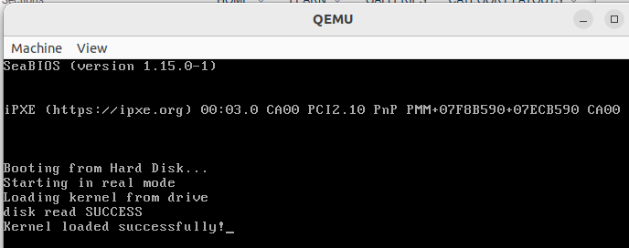
rm -rf *.bin *.o4 Output

Leave a comment
Your email address will not be published. Required fields are marked *