
1 What is Memory Protection?
One main task of an operating system is to isolate programs from each other. Your web browser shouldn’t be able to interfere with your text editor, for example. To achieve this goal, operating systems utilize hardware functionality to ensure that memory areas of one process are not accessible by other processes. There are different approaches depending on the hardware and the OS implementation.
As an example, some ARM Cortex-M processors (used for embedded systems) have a Memory Protection Unit (MPU), which allows you to define a small number (e.g., 8) of memory regions with different access permissions (e.g., no access, read-only, read-write). On each memory access, the MPU ensures that the address is in a region with correct access permissions and throws an exception otherwise. By changing the regions and access permissions on each process switch, the operating system can ensure that each process only accesses its own memory and thus isolates processes from each other.
Memory protection is a system feature that prevents one process from accessing the memory allocated to another process. This safeguard is essential in a multitasking environment where multiple processes run concurrently. Memory protection is enforced by the hardware and supported by the operating system to ensure that each process has its own isolated memory space.
On x86, the hardware supports two different approaches to memory protection: segmentation and paging.
1.1 Segmentation:
Segmentation was already introduced in 1978, originally to increase the amount of addressable memory. The situation back then was that CPUs only used 16-bit addresses, which limited the amount of addressable memory to 64 KiB. To make more than these 64 KiB accessible, additional segment registers were introduced, each containing an offset address. The CPU automatically added this offset on each memory access, so that up to 1 MiB of memory was accessible.
Segment Registers:
- Code Segment (CS): Used for instruction fetching.
- Data Segment (DS): Used for general data access.
- Stack Segment (SS): Used for stack operations (push/pop).
- Extra Segment (ES): Used for additional data access.
Later, two more segment registers, FS and GS, were introduced for flexible use, expanding the versatility of segmentation.
The segment register is chosen automatically by the CPU depending on the kind of memory access: For fetching instructions, the code segment CS is used, and for stack operations (push/pop), the stack segment SS is used. Other instructions use the data segment DS or the extra segment ES. Later, two additional segment registers, FS and GS, were added, which can be used freely.
1.1.1 Early Segmentation:
In the first version of segmentation, the segment registers directly contained the offset and no access control was performed. This basic form of segmentation enabled a simple yet effective way to extend addressable memory but lacked the mechanisms for protecting memory accesses.
1.1.2 Introduction to Protected Mode:
This was changed later with the introduction of the protected mode. When the CPU runs in this mode, the segment descriptors contain an index into a local or global descriptor table, which contains – in addition to an offset address – the segment size and access permissions. By loading separate global/local descriptor tables for each process, which confine memory accesses to the process’s own memory areas, the OS can isolate processes from each other.
The introduction of protected mode brought significant enhancements to segmentation:
- Segment Descriptors: Instead of directly holding offsets, segment registers in protected mode contain indexes pointing to entries in the Global Descriptor Table (GDT) or Local Descriptor Table (LDT).
- Descriptor Tables: These tables hold segment descriptors, which include:
- Base Address: The starting address of the segment.
- Segment Limit: The size of the segment.
- Access Permissions: Permissions defining the allowed types of access (read, write, execute).
By using these descriptor tables, the CPU could enforce access control, ensuring that memory accesses adhered to defined permissions and segment limits. This mechanism enabled the operating system to load different descriptor tables for each process, thereby isolating their memory spaces and preventing unauthorized access.
By modifying the memory addresses before the actual access, segmentation already employed a technique that is now used almost everywhere: virtual memory.
1.1.3 Virtual Memory:
Virtual Memory provides and abstraction layer between logical addresses used by programs and the physical address used by hardware.
The idea behind virtual memory is to abstract away the memory addresses from the underlying physical storage device. Instead of directly accessing the storage device, a translation step is performed first. For segmentation, the translation step is to add the offset address of the active segment. Imagine a program accessing memory address 0x1234000 in a segment with an offset of 0x1111000: The address that is really accessed is 0x2345000.
- Logical Address:
0x1234000 - Segment Offset:
0x1111000 - Physical Address: Logical Address + Segment Offset
- Physical Address Calculation:
0x1234000 + 0x1111000 = 0x2345000
Thus, the logical address 0x1234000 is translated to the physical address 0x2345000.
To differentiate the two address types, addresses before the translation are called virtual, and addresses after the translation are called physical. One important difference between these two kinds of addresses is that physical addresses are unique and always refer to the same distinct memory location. Virtual addresses, on the other hand, depend on the translation function. It is entirely possible that two different virtual addresses refer to the same physical address. Also, identical virtual addresses can refer to different physical addresses when they use different translation functions.
– Virtual Addresses:
- The addresses used by programs to access memory. These addresses are not tied directly to physical memory locations but are instead translated by the system to physical addresses.
- Non-uniqueness: Virtual addresses are not inherently unique. Multiple virtual addresses can map to the same physical address, a process known as aliasing. Conversely, identical virtual addresses in different processes can map to different physical addresses, enabling process isolation.
- Translation Dependency: The translation from virtual to physical addresses is performed by the Memory Management Unit (MMU) using page tables or segment tables. This translation is governed by the operating system's memory management policies.
– Physical Addresses:
- Physical addresses refer to the actual locations in the physical memory hardware (RAM). These addresses are used by the memory controller to access data stored in the memory modules.
- Uniqueness: Physical addresses are unique and consistently refer to specific memory locations. Each physical address corresponds to one distinct location in the RAM.
- Direct Access: Physical addresses are used by the hardware to read or write data to the memory. The operating system and hardware collaborate to ensure that the correct physical addresses are accessed based on the translation of virtual addresses.
An example where this property is useful is running the same program twice in parallel:

Here the same program runs twice, but with different translation functions. The first instance has a segment offset of 100, so that its virtual addresses 0–150 are translated to the physical addresses 100–250. The second instance has an offset of 300, which translates its virtual addresses 0–150 to physical addresses 300–450. This allows both programs to run the same code and use the same virtual addresses without interfering with each other.
Another advantage is that programs can now be placed at arbitrary physical memory locations, even if they use completely different virtual addresses. Thus, the OS can utilize the full amount of available memory without needing to recompile programs.
However, it got a problem known as the Fragmentation:
1.1.4 Fragmentation:
The differentiation between virtual and physical addresses makes segmentation really powerful. However, it has the problem of fragmentation. As an example, imagine that we want to run a third copy of the program we saw above:

There is no way to map the third instance of the program to virtual memory without overlapping, even though there is more than enough free memory available. The problem is that we need continuous memory and can’t use the small free chunks.
One way to combat this fragmentation is to pause execution, move the used parts of the memory closer together, update the translation, and then resume execution:

Now there is enough continuous space to start the third instance of our program.
The disadvantage of this defragmentation process is that it needs to copy large amounts of memory, which decreases performance. It also needs to be done regularly before the memory becomes too fragmented. This makes performance unpredictable since programs are paused at random times and might become unresponsive.
The fragmentation problem is one of the reasons that segmentation is no longer used by most systems. In fact, segmentation is not even supported in 64-bit mode on x86 anymore. Instead, paging is used, which completely avoids the fragmentation problem.
1.2 Paging
The idea is to divide both the virtual and physical memory space into small, fixed-size blocks. The blocks of the virtual memory space are called pages, and the blocks of the physical address space are called frames. Each page can be individually mapped to a frame, which makes it possible to split larger memory regions across non-continuous physical frames.
Basic Concept of Paging:
Paging divides both virtual and physical memory into fixed-size blocks called pages and frames respectively.
- Page: A fixed-size block of virtual memory.
- Frame: A fixed-size block of physical memory.
- Page Table: A data structure used by the operating system to manage the mapping between virtual pages and physical frames.
The advantage of this becomes visible if we recap the example of the fragmented memory space, but use paging instead of segmentation this time:

In this example, we have a page size of 50 bytes, which means that each of our memory regions is split across three pages. Each page is mapped to a frame individually, so a continuous virtual memory region can be mapped to non-continuous physical frames. This allows us to start the third instance of the program without performing any defragmentation before.
1.2.1 Hidden Fragmentation:
Compared to segmentation, paging uses lots of small, fixed-sized memory regions instead of a few large, variable-sized regions. Since every frame has the same size, there are no frames that are too small to be used, so no fragmentation occurs.
Or it seems like no fragmentation occurs. There is still some hidden kind of fragmentation, the so-called internal fragmentation. Internal fragmentation occurs because not every memory region is an exact multiple of the page size. Imagine a program of size 101 in the above example: It would still need three pages of size 50, so it would occupy 49 bytes more than needed. To differentiate the two types of fragmentation, the kind of fragmentation that happens when using segmentation is called external fragmentation.
Internal fragmentation is unfortunate but often better than the external fragmentation that occurs with segmentation. It still wastes memory, but does not require defragmentation and makes the amount of fragmentation predictable (on average half a page per memory region).
1.2.2 Page Tables:
We saw that each of the potentially millions of pages is individually mapped to a frame. This mapping information needs to be stored somewhere. Segmentation uses an individual segment selector register for each active memory region, which is not possible for paging since there are way more pages than registers. Instead, paging uses a table structure called page table to store the mapping information.
For our above example, the page table would look like this:

We see that each program instance has its own page table. A pointer to the currently active table is stored in a special CPU register. On x86, this register is called CR3. It is the job of the operating system to load this register with the pointer to the correct page table before running each program instance.
On each memory access, the CPU reads the table pointer from the register and looks up the mapped frame for the accessed page in the table. This is entirely done in hardware and completely invisible to the running program. To speed up the translation process, many CPU architectures have a special cache that remembers the results of the last translations.
Depending on the architecture, page table entries can also store attributes such as access permissions in a flags field. In the above example, the “r/w” flag makes the page both readable and writable.
1.2.3 Multilevel Page Tables
The simple page tables we just saw have a problem in larger address spaces: they waste memory. For example, imagine a program that uses the four virtual pages 0, 1_000_000, 1_000_050, and 1_000_100 (we use _ as a thousands separator):

It only needs 4 physical frames, but the page table has over a million entries. We can’t omit the empty entries because then the CPU would no longer be able to jump directly to the correct entry in the translation process (e.g., it is no longer guaranteed that the fourth page uses the fourth entry).
To reduce the wasted memory, we can use a two-level page table. The idea is that we use different page tables for different address regions. An additional table called level 2 page table contains the mapping between address regions and (level 1) page tables.
This is best explained by an example. Let’s define that each level 1 page table is responsible for a region of size 10_000. Then the following tables would exist for the above example mapping:

Page 0 falls into the first 10_000 byte region, so it uses the first entry of the level 2 page table. This entry points to level 1 page table T1, which specifies that page 0 points to frame 0.
The pages 1_000_000, 1_000_050, and 1_000_100 all fall into the 100th 10_000 byte region, so they use the 100th entry of the level 2 page table. This entry points to a different level 1 page table T2, which maps the three pages to frames 100, 150, and 200. Note that the page address in level 1 tables does not include the region offset. For example, the entry for page 1_000_050 is just 50.
We still have 100 empty entries in the level 2 table, but much fewer than the million empty entries before. The reason for these savings is that we don’t need to create level 1 page tables for the unmapped memory regions between 10_000 and 1_000_000.
The principle of two-level page tables can be extended to three, four, or more levels. Then the page table register points to the highest level table, which points to the next lower level table, which points to the next lower level, and so on. The level 1 page table then points to the mapped frame. The principle in general is called a multilevel or hierarchical page table.
Now that we know how paging and multilevel page tables work, we can look at how paging is implemented in the x86_64 architecture (we assume in the following that the CPU runs in 64-bit mode).
1.2.4 Example Translation:

The physical address of the currently active level 4 page table, which is the root of the 4-level page table, is stored in the CR3 register. Each page table entry then points to the physical frame of the next level table. The entry of the level 1 table then points to the mapped frame. Note that all addresses in the page tables are physical instead of virtual, because otherwise the CPU would need to translate those addresses too (which could cause a never-ending recursion).
The above page table hierarchy maps two pages (in blue). From the page table indices, we can deduce that the virtual addresses of these two pages are 0x803FE7F000 and 0x803FE00000. Let’s see what happens when the program tries to read from address 0x803FE7F5CE. First, we convert the address to binary and determine the page table indices and the page offset for the address:
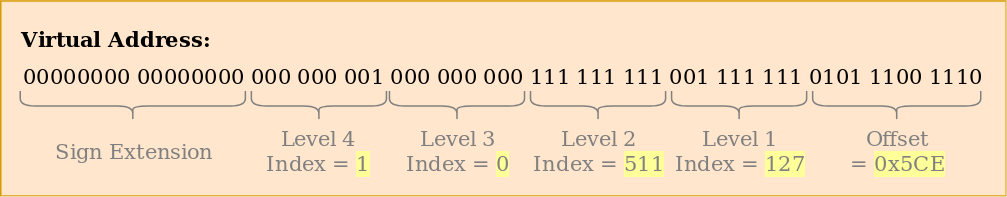
With these indices, we can now walk the page table hierarchy to determine the mapped frame for the address:
- We start by reading the address of the level 4 table out of the
CR3register. - The level 4 index is 1, so we look at the entry with index 1 of that table, which tells us that the level 3 table is stored at address 16 KiB.
- We load the level 3 table from that address and look at the entry with index 0, which points us to the level 2 table at 24 KiB.
- The level 2 index is 511, so we look at the last entry of that page to find out the address of the level 1 table.
- Through the entry with index 127 of the level 1 table, we finally find out that the page is mapped to frame 12 KiB, or 0x3000 in hexadecimal.
- The final step is to add the page offset to the frame address to get the physical address 0x3000 + 0x5ce = 0x35ce.

The permissions for the page in the level 1 table are r, which means read-only. The hardware enforces these permissions and would throw an exception if we tried to write to that page. Permissions in higher level pages restrict the possible permissions in lower levels, so if we set the level 3 entry to read-only, no pages that use this entry can be writable, even if lower levels specify read/write permissions.
It’s important to note that even though this example used only a single instance of each table, there are typically multiple instances of each level in each address space. At maximum, there are:
- one level 4 table,
- 512 level 3 tables (because the level 4 table has 512 entries),
- 512 * 512 level 2 tables (because each of the 512 level 3 tables has 512 entries), and
- 512 * 512 * 512 level 1 tables (512 entries for each level 2 table).
1.2.5 32-bit Paging (x86-32):
Paging is available both in 32 bit and 64 bit mode.
1.2.6 64-bit Paging (x86-64):
x86-64 uses a 4 level paging structure, the levels are:
- PML4 (Page Mapping Level 4)
- PDP (Page Directory Pointer)
- PD (Page Directory)
- and PT (Page Table)

The virtual address space is effectively limited to 48 bits, and the most significant bits (bits 63:48) must be copies of bit 47 due to sign extension. Therefore, the valid virtual address range is from 0x0000_0000_0000_0000 to 0x0000_7FFF_FFFF_FFFF and from 0xFFFF_8000_0000_0000 to 0xFFFF_FFFF_FFFF_FFFF is invalid region.
Let's go through the process of obtaining the address of the PML4 table from the CR3 register and using the subsequent bits for indexing into the paging structures:
- PML4 Index: Bits 47 to 39
- PDP Index: Bits 38 to 30
- PD Index: Bits 29 to 21
- PT Index: Bits 20 to 12
- Page Offset: Bits 11 to 0
Translation Process:
a. Get the Address of the PML4 Table from CR3 Register: - Read the value of the CR3 register to obtain the address of the PML4 table. - This address represents the base address of the PML4 table in physical memory.
b. Extract PML4 Index: - Take bits 47 to 39 from the virtual address. - These bits serve as an index into the PML4 table. - Since there are 512 entries in the PML4 table (2^9), each representing a pointer to a PDP table, the PML4 Index ranges from 0 to 511.
c. Access PDP Table: - Using the PML4 Index, access the corresponding entry in the PML4 table. - Each entry in the PML4 table points to a PDP table.
d. Extract PDP Index: - Take bits 38 to 30 from the virtual address. - These bits serve as an index into the PDP table. - Like the PML4 table, the PDP table also contains 512 entries, each pointing to a Page Directory (PD) table.
e. Access PD Table: - Using the PDP Index, access the corresponding entry in the PDP table. - Each entry in the PDP table points to a PD table.
f. Extract PD Index: - Take bits 29 to 21 from the virtual address. - These bits serve as an index into the PD table. - The PD table contains 512 entries, each pointing to a Page Table (PT).
g. Access PT Table: - Using the PD Index, access the corresponding entry in the PD table. - Each entry in the PD table points to a PT table.
h. Extract PT Index and Page Offset: - Take bits 20 to 12 as the PT Index and bits 11 to 0 as the Page Offset. - The PT Index serves as an index into the PT table, while the Page Offset specifies the offset within the physical page frame.
i. Obtain Physical Address: - Using the PT Index, access the corresponding entry in the PT table to obtain the base address of the physical page frame. - Add the Page Offset to the base address to obtain the complete physical address.
Example: Translating a Virtual Address
Consider a virtual address 0x0000_7FFF_FFFF_1234. We'll break down this address into its components:
- PML4 Index: 0x1FF (bits 47:39)
- PDP Index: 0x1FF (bits 38:30)
- PD Index: 0x1FF (bits 29:21)
- PT Index: 0x1FF (bits 20:12)
- Page Offset: 0x1234 (bits 11:0)
Now, let's go through the translation process step by step:
1. Get the Address of the PML4 Table from CR3 Register:
- Assume the CR3 register holds the address
0xFFFF_FFFF_FFFF_9000, which points to the base of the PML4 table.
2. Extract PML4 Index:
- Take bits 47:39 from the virtual address: 0x1FF.
- Use this index to access the corresponding entry in the PML4 table.
3. Access PDP Table:
- The entry in the PML4 table at index 0x1FF points to the base address of the PDP table.
- Let's say the PDP table's base address is
0xFFFF_FFFF_FFFF_A000.
4. Extract PDP Index:
- Take bits 38:30 from the virtual address: 0x1FF.
- Use this index to access the corresponding entry in the PDP table.
5. Access PD Table:
- The entry in the PDP table at index 0x1FF points to the base address of the PD table.
- Let's say the PD table's base address is
0xFFFF_FFFF_FFFF_B000.
6. Extract PD Index:
- Take bits 29:21 from the virtual address: 0x1FF.
- Use this index to access the corresponding entry in the PD table.
7. Access PT Table:
- The entry in the PD table at index 0x1FF points to the base address of the PT table.
- Let's say the PT table's base address is
0xFFFF_FFFF_FFFF_C000.
8. Extract PT Index and Page Offset:
- Take bits 20:12 as the PT Index: 0x1FF.
- Take bits 11:0 as the Page Offset: 0x1234.
9. Obtain Physical Address:
- Use the PT Index to access the corresponding entry in the PT table, which contains the base address of the physical page frame.
- Add the Page Offset to the base address to obtain the complete physical address.
2 What is Long Mode?
Long mode is a term used in x86-64 (also known as x64) architecture that refers to the mode in which a 64-bit processor operates, enabling it to handle 64-bit instructions and addressing. This mode was introduced by AMD with the release of their AMD64 architecture, and later adopted by Intel with their Intel 64 architecture. Long mode essentially expands the capabilities of the processor beyond the 32-bit limitations that were standard in previous x86 architectures.
3 Components of Long Mode
Long mode consists of two sub-modes:
- 64-bit Mode: This mode allows the execution of 64-bit instructions, enabling the processor to utilize 64-bit general-purpose registers and a 64-bit address space. This significantly increases the amount of addressable memory, theoretically up to 16 exabytes, though current implementations limit this to a lower value due to practical constraints.
- Compatibility Mode: This mode allows the processor to run 16-bit and 32-bit applications on a 64-bit operating system. It ensures backward compatibility, enabling users to run older software without modification.
4 Key Features of Long Mode
1 Extended Registers:
- 64-bit General-Purpose Registers: Registers such as RAX, RBX, RCX, RDX, RSI, RDI, RBP, and RSP are extended to 64 bits. Additionally, eight new registers (R8 to R15) are introduced.
- Instruction Pointer (RIP): The instruction pointer is extended to 64 bits, allowing for a significantly larger addressable space.
2 64-bit Virtual Address Space:
- Address Space: The virtual address space is expanded to 64 bits, though current implementations use up to 48 bits for virtual addresses, providing 256 TiB of addressable space.
- Canonical Form Addresses: Only the lower 48 bits are used, with higher bits being a sign-extension of bit 47, ensuring addresses are in canonical form.
3 Enhanced Paging:
- Four-Level Paging: Supports a hierarchical four-level paging structure (PML4, PDPT, Page Directory, Page Table) to manage the large address space.
- Large Pages: Supports 4 KiB, 2 MiB, and 1 GiB page sizes, allowing flexible and efficient memory management.
4 Compatibility Mode:
- Legacy Code Execution: Allows 16-bit and 32-bit applications to run on a 64-bit operating system without modification.
- Segmentation: In compatibility mode, segmentation behaves similarly to how it does in protected mode.
5 Extended Instruction Set:
- New Instructions: Long mode introduces new instructions and extends existing ones to take advantage of the 64-bit registers and address space.
- SIMD Enhancements: Includes enhancements to the SIMD (Single Instruction, Multiple Data) instruction set, such as SSE (Streaming SIMD Extensions) and AVX (Advanced Vector Extensions).
5 Transitioning to Long Mode
Transitioning a processor to long mode involves several steps and conditions:
- Enabling Paging: Long mode requires paging to be enabled. Paging is a memory management scheme that eliminates the need for contiguous memory allocation, thus allowing the efficient use of memory.
- Setting Up Page Tables: Proper page tables must be established, specifically PML4 (Page Map Level 4) tables, which map the 64-bit address space.
- Enabling Long Mode: The
EFER(Extended Feature Enable Register) MSR (Model Specific Register) must be set to enable long mode. - Switching to 64-bit Mode: Finally, the processor must switch to 64-bit mode by setting the
LME(Long Mode Enable) bit in theCR0register.
5.1 Checking CPU Support for Long Mode
5.1.1 Check Support for cpuid instruction:
- In order to check for long mode support, we have to check if it
cpuidinstruction is supported.
;=============================================================================
; HasCPUID
;
; Detect if the cpu supports the CPUID instruction.
;
; Bit 21 of the EFLAGS register can be modified only if the CPUID instruction
; is supported.
;
; Return flags:
;   CF      Set if CPUID is supported
;
; Killed registers:
;   None
;=============================================================================
HasCPUID:

  ; Preserve registers.
  push    eax
  push    ecx

  ; Copy flags to eax and ecx.
  pushfd
  pop     eax
  mov     ecx,    eax

  ; Set flag 21 (the ID bit)
  xor     eax,    (1 << 21)
  push    eax
  popfd

  ; Copy flags back to eax. If CPUID is supported, bit 21 will still be set.
  pushfd
  pop     eax

  ; Restore the original flags from ecx.
  push    ecx
  popfd

  ; Initialize the return flag (carry) to unsupported.
  clc

  ; If eax and ecx are equal, then flag 21 didn't remain set, and CPUID is
  ; not supported.
  xor     eax,    ecx
  jz      .done       ; CPUID is not supported

  .supported:

    ; CPUID is supported.
    stc

  .done:

    ; Restore registers.
    pop     ecx
    pop     eax

    ret
Explanation:
1 Preserve Registers:
push    eax
push    ecx
- The current values of
EAXandECXare saved on the stack to preserve their contents for later use.
2 Copy Flags to EAX and ECX:
pushfd
pop     eax
mov     ecx, eax
- The current EFLAGS register is pushed onto the stack
pushfd. - The EFLAGS register is then popped into
EAX. - The value in
EAXis copied toECXfor later comparison.
3 Set the ID Bit (Bit 21):
xor     eax, (1 << 21)
push    eax
popfd
- Bit 21 of
EAXis toggled using XOR operation with(1<<21), which sets the ID bit. - The modified
EAXis pushed onto the stack and then popped into the EFLAGS register to update the flags.
4 Copy Flags Back to EAX:
pushfd
pop     eax
- The modified EFLAGS register is pushed onto the stack again and then popped into
EAXto check if the ID bit is still set.
5 Restore the Original Flags from ECX:
push    ecx
popfd
- The original EFLAGS value saved in
EAXis pushed back onto the stack and then popped into the EFLAGS register to restore the original flags.
6 Initialize the Return Flag (Carry) to Unsupported:
clc- The carry flag (CF) is cleared to indicate that CPUID is not supported by default.
7 Check if the ID Bit Remained Set:
xor     eax, ecx
jz      .done
- The value in
EAX(modified flags) is XORed with the value inECX(original flags). - If the values are the same, the result will be zero (
EAX == ECX), meaning the ID bit could not be toggled, so CPUID is not supported. The code jumps to.done.
8 Set Carry Flag if CPUID is Supported:
.supported:
stc
- If the ID bit was successfully toggled (
EAX != ECX), the code sets the carry flag (CF) to indicate CPUID is supported.
9 Restore Registers and Return:
.done:
pop     ecx
pop     eax
ret
- The original values of
ECXandEAXare restored from the stack. - The function returns, with the carry flag indicating whether CPUID is supported.
5.1.2 Check If Processor Info Supported:
; Load EAX with the value 0x80000000 to query the CPUID function for the highest extended function supported
mov     eax,    0x80000000

; Invoke the CPUID instruction to retrieve processor information
cpuid

; Compare the value in EAX (highest extended function supported) with 0x80000001
cmp     eax,    0x80000001

; If the highest extended function supported is less than 0x80000001, jump to .error.no64BitMode
jb      .error.no64BitMode
mov eax, 0x80000000: This instruction moves the value0x80000000into the EAX register. This value is used as an input to the CPUID instruction to retrieve information about the highest extended function supported by the processor.cpuid: This instruction invokes the CPUID instruction, which returns information about the processor. Upon execution, the CPUID instruction updates several registers with specific information, including the highest extended function supported, which will be stored in the EAX register.cmp eax, 0x80000001: After the CPUID instruction has been executed, this line compares the value stored in the EAX register (which now holds information about the highest extended function supported) with0x80000001. This comparison is performed to check if the CPU supports an extended function with the function ID0x80000001.jb .error.no64BitMode: Jump toerror.no64BitModeif less than0x80000001. Meaning, 64 bit mode is not supported.- If the value in EAX is greater than or equal to
0x80000001, it means that the CPU supports the extended function with the ID0x80000001, which typically provides processor information. Conversely, if the value in EAX is less than0x80000001, it indicates that the CPU does not support the function with that ID, and therefore processor information retrieval might not be supported.
5.1.3 Check Long Mode:
; Use the CPUID instruction with function ID 0x80000001 to retrieve extended processor info and feature bits
mov     eax,    0x80000001

; Invoke the CPUID instruction to retrieve the extended processor information
cpuid

; Test the 64-bit mode bit (bit 29) in the EDX register
test    edx,    (1 << 29)

; If the 64-bit mode bit is not set (zero), jump to .error.no64BitMode
jz      .error.no64BitMode
This code segment checks if the processor supports 64-bit mode by examining the appropriate bit in the EDX register after invoking the CPUID instruction with function ID 0x80000001. If the 64-bit mode bit (bit 29) in the EDX register is not set (zero), it implies that 64-bit mode is not supported, and the program branches to handle this scenario.
5.2

Leave a comment
Your email address will not be published. Required fields are marked *