
To get familiar with things refer to this article first: https://thejat.in/learn/interrupts-idt-isr-and-irq
Well there are two techniques by which a hardware get attention of the processor:
1️⃣ Interrupts:
Interrupts are signals sent to the CPU by external devices or internal events indicating that they require immediate attention. When an interrupt is received, the CPU stops executing its current instructions, saves its state, and begins executing a special function called an interrupt handler or interrupt service routine (ISR) to address the specific event. After the ISR is completed, the CPU resumes its previous tasks.
Consider a real life example:
Imagine you are working in an office. You are doing your daily work like completing a report. Suddenly, the fire alarm goes off.
The fire alarm system acts as an interrupt. When the alarm sounds, it interrupts whatever you are doing immediately captures your attention. You stop working and evacuate the building according to the fire drill procedure.
- Similar to how the fire alarm interrupts your activity, a hardware interrupt in a computer system causes the CPU to stop its current tasks and immediately address the interrupting device or situation, such as handling an incoming network packet or a key press on the keyboard.
Key Characteristics:
- Asynchronous: Interrupts can occur at any time, independent of the CPU’s current activities.
- Priority Levels: Some interrupts have higher priority and can preempt others.
- Efficiency: Interrupts allow the CPU to handle events and tasks more efficiently by not wasting time checking device statuses continually.
Example:
- A keyboard press generates an interrupt to inform the CPU that a key has been pressed, requiring the CPU to read the keystroke data.
2️⃣ Polling:
Polling is a technique where the CPU continuously checks the status of a peripheral device at regular intervals to see if it requires attention. The CPU actively waits and repeatedly queries the device, executing the necessary tasks only when the device is ready.
Consider a real life example:
You are expecting a package delivery. You frequently check your front door to see if the package has arrived.
- Instead of waiting for a notification (like an interrupt), you periodically get up and check the door.
- You do this multiple times throughout the day, regardless of whether the package has arrived or not.
- Polling in a computer system is like your periodic checks for the package.
- The CPU continuously checks the status of a peripheral device at regular intervals to see if it needs attention, such as checking if a printer is ready or if there's new data from a sensor.
Key Characteristics:
- Synchronous: Polling occurs at predictable intervals as part of the CPU’s routine.
- CPU Usage: Polling can be inefficient as it consumes CPU time even when the device does not need service.
- Simpler Implementation: Polling mechanisms are often simpler to implement than interrupt-driven mechanisms.
Example:
- A CPU continuously checks the status of a printer to see if it is ready to receive more data, regardless of whether there is any pending data to be sent.
Programmable Interrupt Controller (PIC)
A Programmable Interrupt Controller (PIC) is a device used in computers to manage interrupt requests (IRQs) from hardware devices. The PIC is responsible for handling multiple interrupt lines from devices, prioritizing them, and then sending interrupt signals to the CPU. In x86 architecture, the most commonly known PIC is the Intel 8259A.
In x86 systems, the original IBM PC used a single Intel 8259A PIC. Later systems often use a pair of cascaded 8259A PICs to handle more interrupts. Modern system has APIC (Advanced Programmable Interrupt Controller) which is essentially an extended version of the old PIC chip to maintain backwards compatibility.
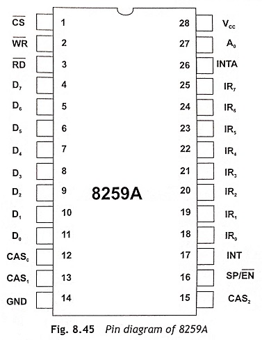
Single 8259A PIC:
- Handles up to 8 interrupt lines (IRQ0 to IRQ7).
Cascaded 8259A PICs:
- Allows for 15 interrupt lines (IRQ0 to IRQ15) with IRQ2 used to cascade the second PIC.
Ports and Commands:
The 8259A PIC is controlled via I/O ports. Here are some key ports and commands:
1 Command Port (0x20 for master, 0xA0 for slave):
- Used to send commands to the PIC.
2 Data Port (0x21 for master, 0xA1 for slave):
- Used to read/write interrupt masks and other data.
Working of 8259A
The function of the 8259A is actually relatively simple. Each PIC has 8 input lines, called Interrupt Requests (IRQ), numbered from 0 to 7. When any of these lines goes high (fired an interrupt), the PIC alerts the CPU and sends the appropriate interrupt number. This number is calculated by adding the IRQ number (0 to 7) to an internal "vector offset" value. The CPU uses this value to execute an appropriate Interrupt Service Routine.
Well It's not quite as simple as that, because each system has two PICS, a "master" and a "slave". So when the slave raises an interrupt, it's actually sent to the master, which sends that to the CPU. In this way, interrupts cascade and a processor can have 16 IRQ lines. Of these 16, one is needed for the two PIC chips to interface with each other, so the number of available IRQs is decreased to 15.

cli and sti:
We have cli and sti instructions to disable and enable all hardware interrupts. However it's sometimes desirable to selectively disable particular interrupt of certain devices. For this purpose, PICs have an internal 8-bit register called Interrupt Mask Register (IMR). The bits in this register determine which IRQs are passed on to the CPU. If an IRQs is fired but the corresponding bit in the IMR is set, it is ignored and nothing is sent to the CPU.
Detailed Working:
            +---------------------------+
            |                           |
            |         CPU               |
            |                           |
            +-----------+---+-----------+
                        ^   ^
                        |   | Interrupt Vector
                        |   |
                        |   |
            +-----------+---+-----------+
            |         8259A PIC         |
            +---------------------------+
            |    Control Logic          |
            +---------------------------+
            | Priority Resolver         |
            +---------------------------+
            | IMR   | IRR   | ISR       |
            +-------+-------+-----------+
            |   Interrupt Request Lines |
            | IRQ0 IRQ1 ...  IRQ7       |
            +---------------------------+
1 Interrupt Request:
- A hardware device sends an interrupt signal to one of the IRQ lines (e.g., IRQ0 for a timer, IRQ1 for a keyboard).
2 Interrupt Recognition:
- The PIC recognizes the interrupt and sets the corresponding bit in the Interrupt Request Register (IRR).
3 Priority Resolution:
- The Priority Resolver determines the highest-priority interrupt among the set bits in the IRR.
4 Interrupt Masking:
- If the interrupt is not masked in the Interrupt Mask Register (IMR), the PIC proceeds to handle it.
5 Interrupt Acknowledgment:
- The PIC sends an interrupt vector to the CPU, informing it of the interrupt.
- The CPU uses this vector to index into the Interrupt Vector Table (IVT) to find the address of the Interrupt Service Routine (ISR).
6 In-Service Register:
- The corresponding bit in the In-Service Register (ISR) is set, indicating the interrupt is being serviced.
7 Executing ISR:
- The CPU jumps to the ISR address and executes the interrupt handling code.
8 End of Interrupt (EOI):
- After the ISR completes, the CPU sends an EOI command to the PIC via the OCW2 register.
- The PIC clears the corresponding bit in the ISR, indicating the interrupt has been serviced.
Cascading Multiple PICs:
In systems requiring more than 8 interrupts, multiple 8259A PICs can be cascaded. A common configuration uses two 8259A PICs:
- Master PIC: Handles IRQ0 to IRQ7.
- Slave PIC: Handles IRQ8 to IRQ15, connected to one of the Master PIC’s IRQ lines (usually IRQ2).
                +---------------------------+
                |         CPU               |
                +---------------------------+
                            |
                            v
                +-----------+------------+
                |       Master PIC       |
                +-----------+------------+
                | IRQ0      |       IRQ7 |
                | IRQ1      |       IRQ6 |
                | ...       |       ...  |
                | IRQ2 -> Slave PIC      |
                +-------------------------+
                            |
                            v
                +-----------+-----------+
                |       Slave PIC       |
                +-----------+-----------+
                | IRQ8      |      IRQ15|
                | IRQ9      |      IRQ14|
                | ...       |      ...  |
                +-------------------------+
Some Information:
Interrupt Vector: An interrupt vector is a unique identifier assigned to each interrupt or exception in the system. It is used to index into the Interrupt Descriptor Table (IDT) to find the appropriate interrupt descriptor, which in turn points to the handler (ISR) for that specific interrupt or exception. Ex: int 0x2, here 0x2 is the interrupt vector.
Interrupt Request: A term used to describe interrupts that are sent to the Programmable Interrupt Controller. Each IRQ has a specific number associated with it, which is used to identify the type of interrupt and index into the IDT. The PIC was deprecated long ago and has since been replaced by the APIC. An IRQ refers to the pin number used on the PIC: for example, IRQ2 would be pin #2. The APIC has a chapter of its own.
Interrupt Service Routine: An Interrupt Service Routine is a special type of function or subroutine that handles interrupts or exceptions generated by hardware or software. When an interrupt occurs, the CPU transfers control to the appropriate ISR based on the interrupt vector. ISRs are responsible for servicing the interrupt, saving necessary state, and returning control to the interrupted program once the interrupt is handled.
Interrupt Descriptor: A single entry within the interrupt descriptor table. It provides information such as the base address of the handler code, the code segment selector, and access privileges.
Interrupt Descriptor Table (IDT): A data structure (or array) of Interrupt descriptors. Each entry in the IDT points to the handler (Interrupt Service Routine or ISR) for a specific interrupt or exception.
Interrupt Descriptor Table Register (IDTR): The IDTR is a special register in x86 processors that holds the base address and limit of the Interrupt Descriptor Table (IDT). It allows the processor to locate the IDT in memory quickly when an interrupt or exception occurs.
Implement IDT and ISR for Divide by Zero Exception
We will implement the divide by zero exception.
For this we will set up interrupt descriptor table.
Ⅰ Define the IDT Structure:
The IDT is a data structure used by the x86 architecture to define interrupt service routines (ISRs). Each entry in the IDT corresponds to an interrupt vector.
IDT Structure in Assembly:
First, create the IDT structure in assembly. As we all know that IDT structure is quite similar to the GDT structure.
IDT (Interrupt Descriptor Table): It contains the entries which contains the ISR address of interrupt which is called when then particular indexed error occurs, along with ISR address it contains the privileges and some flags. When can simply call IDT as an array of 8-byte entries, where each entry corresponds to a specific interrupt or exception.
Each entry typically contains:
- Offset: The address of the interrupt or exception handler function.
- Segment Selector: The code segment selector associated with the handler function.
- Type and Attributes: Flags specifying the type of interrupt gate (e.g., interrupt gate, trap gate) and privilege level (e.g., kernel module).
// IDT entry structure 8 bytes
struct idt_entry {
    unsigned short offset_low;    // Offset bits 0-15
    unsigned short selector;      // Code segment selector
    unsigned char zero;           // Always 0
    unsigned char type_attr;      // Type and attributes
    unsigned short offset_high;   // Offset bits 16-31
} __attribute__((packed));

#define IDT_SIZE 256 	; There are total 256 interrupts possible

// IDT array
struct idt_entry idt[IDT_SIZE];
Ⅱ IDT Pointer Structure:
In x86 architecture, the Interrupt Descriptor Table (IDT) Pointer (IDTR) is a special register used to load the base address and limit of the Interrupt Descriptor Table (IDT). The IDT is a data structure that contains entries for various interrupt vectors, each describing how the CPU should handle a specific interrupt or exception.
Purpose of the IDT Pointer
The IDT Pointer (IDTR) serves two main purposes:
- Specifies the Location of the IDT: It contains the base address and the limit of the IDT. The base address points to the start of the IDT in memory, and the limit specifies the size of the IDT in bytes.
- Allows the CPU to Locate Handlers: When an interrupt or exception occurs, the CPU uses the
IDTRto find the appropriate handler function defined in the IDT. The handler function is executed to handle the interrupt or exception.
Structure of the IDT Pointer
The IDT Pointer (IDTR) is a 48-bit register, consisting of two components:
- Base Address: This is a 32-bit field that holds the linear address (virtual address) where the IDT starts in memory.
- Limit: This is a 16-bit field that specifies the size of the IDT in bytes, minus 1. In other words, it determines the maximum offset within the IDT.
// IDT pointer structure
struct idt_ptr {
    unsigned short limit; // Limit of the IDT
    unsigned int base;  // Base address of the IDT
} __attribute__((packed));
Ⅲ Function to Load the IDT in IDT Pointer:
The IDT Pointer (IDTR) is a special register in the CPU that holds the base address and limit of the IDT.
Assembly function to Load IDT (lidt).
; Interrupt Descriptor Table
global idt_load
extern idtp		; idtp is the structure we defined in c code (idt.c)
idt_load:
	lidt [idtp]
	ret
Ⅳ Install the IDT:
/*
 * IDT Entry
 */
struct idt_entry {
	unsigned short base_low;   // Lower 16 bits of the handler function's address
	unsigned short sel;        // Kernel segment selector
	unsigned char zero;        // Always zero
	unsigned char flags;       // Type and attributes of the interrupt gate
	unsigned short base_high;  // Upper 16 bits of the handler function's address
} __attribute__((packed));

struct idt_ptr {
	unsigned short limit;      // Size of the IDT - 1
	unsigned int base;         // Base address of the IDT
} __attribute__((packed));

struct idt_entry idt[256];    // Array to store 256 IDT entries
struct idt_ptr idtp;          // Pointer to the IDT

extern void idt_load();       // Assembly function to load the IDT


/*
 * memset
 * Set `count` bytes starting at `dest` to `val`.
 */
unsigned char *memset(unsigned char *dest, unsigned char val, int count) {
	int i;
	i = 0;
	for ( ; i < count; ++i ) {
		dest[i] = val;
	}
	return dest;
}

/*
 * idt_install
 * Install the IDTs by setting up the IDT pointer, clearing the IDT, and loading the IDT.
 */
void idt_install() {
	idtp.limit = (sizeof(struct idt_entry) * 256) - 1;     // Calculate the limit of the IDT
	idtp.base = (unsigned int)&idt;                       // Set the base address of the IDT to the address of `idt`
	memset((unsigned char *)&idt, 0, sizeof(struct idt_entry) * 256);  // Clear the IDT entries

	idt_load();                                           // Load the IDT by calling the assembly function
}
Explanation:
- IDT Entry Struct (
struct idt_entry):- Defines the structure of each IDT entry, specifying the lower and upper parts of the handler function's address (
base_lowandbase_high), the segment selector (sel), flags (flags), and a reserved byte (zero).
- Defines the structure of each IDT entry, specifying the lower and upper parts of the handler function's address (
- IDT Pointer Struct (
struct idt_ptr):- Defines the structure for the IDT Pointer (
idtp), which includes the limit (size of the IDT - 1) and the base address of the IDT.
- Defines the structure for the IDT Pointer (
- Arrays and Extern Declaration:
idt[256]: Array to store 256 IDT entries.idtp: Variable of typestruct idt_ptrto store the IDT Pointer.extern void idt_load();: Declaration of an external assembly function (idt_load) responsible for loading the IDT.
- Memory Utility Function (
memset):- Implements a simple memory setting function to initialize memory regions, which is used here to clear the IDT entries before installation.
- IDT Installation Function (
idt_install):- Sets up the IDT Pointer (
idtp) with the size and base address ofidt. - Clears all IDT entries using
memset. - Calls
idt_load()to load the IDT using an assembly routine.
- Sets up the IDT Pointer (
Ⅴ Installing the ISR for Divide by Zero Exception:
/*
 * idt_set_gate
 * Set an IDT gate with the provided parameters.
 */
void idt_set_gate(unsigned char num, unsigned long base, unsigned short sel, unsigned char flags) {
	idt[num].base_low =     (base & 0xFFFF);              // Set lower 16 bits of base address
	idt[num].base_high =    (base >> 16) & 0xFFFF;        // Set upper 16 bits of base address
	idt[num].sel =          sel;                          // Set segment selector
	idt[num].zero =         0;                            // Always zero
	idt[num].flags =        flags;                        // Set flags (type and attributes)

// Flags = 0x8E
/*
Bit  7 6 5 4 3 2 1 0
     1 0 0 0 1 1 1 0

*/

/*
* Present (P) bit: Bit 7. This must be set to 1, indicating that the interrupt gate is present.
* Descriptor Privilege Level (DPL): Bits 6-5. This specifies the privilege level required to access this interrupt. For kernel-level interrupts, this is typically set to 0.
* Storage Segment (S) bit: Bit 4. This must be set to 0 for interrupt and trap gates.
* Gate Type: Bits 3-0. This specifies the type of gate. For 32-bit interrupt gates, this should be set to 0b1110 (14).

Combining these fields, a typical flags value for a kernel-level interrupt gate (privilege level 0) would be 0x8E:

** Present: 1 (bit 7)
** DPL: 00 (bits 6-5)
** S: 0 (bit 4)
** Gate Type: 1110 (bits 3-0)

*/
}- IDT Setting Function (
idt_set_gate):- Sets an IDT gate (
idt[num]) with the provided parameters:num(entry number),base(handler function's address),sel(segment selector), andflags(type and attributes).
- Sets an IDT gate (
ISR for the Exception Handler:
; Interrupt Service Routines
global _isr0

; ISR 0: Divide By Zero Exception Handler
_isr0:
    cli                    ; Disable interrupts

    ; Pushing 0 and interrupt number onto the stack
    push byte 0
    push byte 0            ; Interrupt number (0 for Divide By Zero)

    ; Jump to common ISR stub
    jmp isr_common_stub

extern fault_handler      ; External symbol for fault_handler

; Common ISR Stub
isr_common_stub:
    pusha           ; Push all general-purpose registers
    				; pusha pushes the general-purpose registers
    				; in the following order:
    				; EAX, ECX, EDX, EBX, original ESP, EBP, ESI, EDI.
    				; |..previous stack..|
    				; | Return Address	 |
    				; |	EDI 			 |
    				; | ESI				 |
    				; | EBP				 |
    				; | Original ESP	 |
    				; | EBX				 |
					; |	EDX				 |
    				; | ECX				 |
    				; | EAX				 | <- Stack pointer


    push ds                 ; Push DS, ES, FS, GS registers
    push es
    push fs
    push gs
    				; |..previous stack..|
    				; | Return Address	 |
    				; |	EDI 			 |
    				; | ESI				 |
    				; | EBP				 |
    				; | Original ESP	 |
    				; | EBX				 |
					; |	EDX				 |
    				; | ECX				 |
    				; | EAX				 |
    				; |	DS				 |
    				; | ES				 |
    				; | FS				 |
    				; | GS				 | <- stack pointer

    mov ax, 0x10            ; Load data segment selector (0x10 is typically kernel data segment)
    mov ds, ax
    mov es, ax
    mov fs, ax
    mov gs, ax

    mov eax, esp    ; Save current stack pointer into EAX
    push eax        ; Push it onto the stack
    				; |..previous stack..|
    				; | Return Address	 |
    				; |	EDI 			 |
    				; | ESI				 |
    				; | EBP				 |
    				; | Original ESP	 |
    				; | EBX				 |
					; |	EDX				 |
    				; | ECX				 |
    				; | EAX				 |
    				; |	DS				 |
    				; | ES				 |
    				; | FS				 |
    				; | GS				 |
    				; |ESP(pointer to DS)| <- ESP

    mov eax, fault_handler  ; Load address of fault_handler function into EAX
    call eax                ; Call fault_handler function
    				; |..previous stack..|
    				; | Return Address	 |
    				; |	EDI 			 |
    				; | ESI				 |
    				; | EBP				 |
    				; | Original ESP	 |
    				; | EBX				 |
					; |	EDX				 |
    				; | ECX				 |
    				; | EAX				 |
    				; |	DS				 |
    				; | ES				 |
    				; | FS				 |
    				; | GS				 |
    				; |	ESP(pointer to DS)|
    				; | Return Address to ISR| <- ESP (now pointing to the return address for the `fault_handler`)

    pop eax                 ; Pop the original stack pointer back into EAX

    pop gs                  ; Pop GS, FS, ES, DS registers
    pop fs
    pop es
    pop ds

    popa                    ; Pop all general-purpose registers
    add esp, 8              ; Clean up stack (remove pushed interrupt number)
    iret                    ; Return from interrupt
Explanation:
_isr0Label:- This is the entry point for handling the divide by zero exception (
ISR 0). When a divide by zero exception occurs, the CPU will jump to this label to begin handling the exception.
- This is the entry point for handling the divide by zero exception (
cliInstruction:clidisables interrupts. This ensures that while handling this exception, no other interrupts will interrupt the current exception handling process.
- Pushing Interrupt Number:
- Two
push byteinstructions push0onto the stack. This represents the interrupt number (0) and is typically used by the fault handler to identify the type of interrupt.
- Two
- Jump to
isr_common_stub:jmp isr_common_stubtransfers control to a common ISR stub (isr_common_stub), which sets up the environment and callsfault_handler.
isr_common_stub:- Environment Setup:
pushapushes all general-purpose registers onto the stack to save their state.push ds,push es,push fs,push gspush segment registers onto the stack to save their state.
- Segment Selector Setup:
mov ax, 0x10loads the kernel data segment selector (0x10typically represents the kernel data segment).mov ds, ax,mov es, ax,mov fs, ax,mov gs, axsets DS, ES, FS, GS registers to the kernel data segment.
- Stack Pointer Setup:
mov eax, espcopies the current stack pointer into EAX.push eaxpushes the stack pointer onto the stack, preparing it for use byfault_handler.
- Calling
fault_handler:mov eax, fault_handlerloads the address offault_handlerinto EAX.call eaxcalls thefault_handlerfunction, passing it the address of the saved stack pointer.
- Stack and Register Cleanup:
pop eaxrestores the original stack pointer from before callingfault_handler.pop gs,pop fs,pop es,pop dsrestore segment registers.poparestores all general-purpose registers from the stack.add esp, 8cleans up the stack by removing the two pushed bytes representing the interrupt number.
- Return from Interrupt:
iretis used to return from the interrupt handling routine, restoring the saved state of the CPU before the interrupt occurred.
- Environment Setup:
/* Registers */
struct regs {
unsigned int gs, fs, es, ds; // Segment registers
unsigned int edi, esi, ebp, esp, ebx, edx, ecx, eax; // General-purpose registers
unsigned int int_no, err_code; // Interrupt number and error code
unsigned int eip, cs, eflags, useresp, ss; // Processor state
};
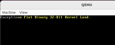
void fault_handler(struct regs *r) {
if (r->int_no < 32) {
char* vMem = (char*) 0xb8000;
vMem[0] = 'E';
vMem[1] = 0x07;
vMem[2] = 'x';
vMem[3] = 0x07;
vMem[4] = 'c';
vMem[5] = 0x07;
vMem[6] = 'e';
vMem[7] = 0x07;
vMem[8] = 'p';
vMem[9] = 0x07;
vMem[10] = 't';
vMem[11] = 0x07;
vMem[12] = 'i';
vMem[13] = 0x07;
vMem[14] = 'o';
vMem[15] = 0x07;
vMem[16] = 'n';
vMem[17] = 0x07;
for (;;);
}
}Breakdown of fault_handler:
- Check Interrupt Number:
if (r->int_no < 32): This checks if the interrupt number is less than 32, which corresponds to CPU exceptions.
- Writing to Video Memory:
char* vMem = (char*) 0xb8000;: The address0xb8000is the start of video memory for text mode on x86 systems. Each character on the screen is represented by two bytes: one for the ASCII character and one for its attribute (color).- The following lines write the string "Exception" to the video memory. Each character is followed by
0x07, which sets the attribute for white text on a black background.
Infinite Loop:
for (;;);: This infinite loop halts the system by preventing it from continuing execution. This is a typical way to stop the system after a critical fault.
void isrs_install() {
	/* Exception Handlers */
	idt_set_gate(0, (unsigned)_isr0, 0x08, 0x8E);
}
Output

Leave a comment
Your email address will not be published. Required fields are marked *