
In the previous chapter, we have seen how to transition from the text mode to the graphics mode. We have switched to the mode 0x13 which has 320x200 resolution with 256 colors.
Understanding Graphics Mode
In BIOS bootloader development, the system starts in text mode, where characters are rendered on a character grid. However, the BIOS also supports graphics mode, which allows for more complex graphical rendering. One of the most common graphics modes used in BIOS bootloader development is Mode 0x13. Mode 0x13 is a 320x200 resolution graphics mode with 256 colors.
Setting Up Graphics Mode
To set up graphics mode in a BIOS bootloader, we need to use BIOS interrupts. In x86 assembly language, the int 0x10 instruction is used to interact with the BIOS video services. To set the system to Mode 0x13, we set the AX register to 0x0013 and then call the int 0x10 instruction.
start:
    mov ax, 0x0013 ; Set video mode 0x13 (320x200, 256 colors)
    int 0x10       ; BIOS interrupt to set video mode
Plotting a Pixel
Once the system is set to graphics mode, we can start drawing graphics on the screen. To draw graphics, we need to write directly to the video memory. In Mode 0x13, the video memory starts at address 0xA0000. Each pixel on the screen corresponds to a single byte in video memory.
To draw a pixel at coordinates (x, y) with color color, we calculate the offset into video memory using the formula offset = y * 320 + x, where 320 is the width of the screen in pixels.
; Function to draw a pixel at (CX, DX) with color AX
draw_pixel:
    mov ah, 0x0C   ; BIOS function to plot a pixel
    int 0x10       ; BIOS interrupt
    ret
Example:
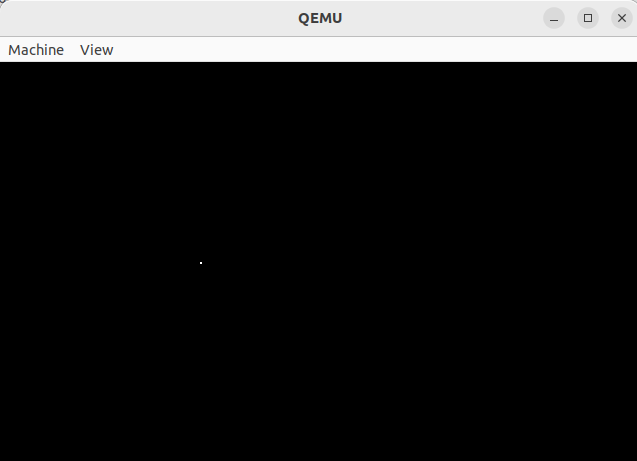
Let's draw a white pixel at coordinates (100, 200):
mov al, 0x0F ; Color (white)
mov cx, 100    ; X coordinate
mov dx, 100    ; Y coordinate
call draw_pixel
Complete Code:
; Set up basic graphics mode (320x200, 256 colors) in BIOS bootloader

BITS 16            ; 16-bit real mode
ORG 0x7C00         ; Bootloader entry point

start:
    mov ax, 0x0013 ; Set video mode 0x13 (320x200, 256 colors)
    int 0x10       ; BIOS interrupt to set video mode

    ; Draw a pixel at coordinates (100, 100) with color 0x0F (white)
    mov al, 0x0F   ; Color (white)
    mov cx, 100    ; X coordinate
    mov dx, 100    ; Y coordinate
    call draw_pixel

    jmp $          ; Infinite loop

; Function to draw a pixel at (CX, DX) with color AL
draw_pixel:
    pusha
    mov ah, 0x0C   ; BIOS function to plot a pixel
    int 0x10       ; BIOS interrupt
    popa
    ret

TIMES 510 - ($ - $$) db 0 ; Fill the rest of the bootloader sector with zeros
DW 0xAA55                 ; Boot signature
Output:
Explanation:
1 Set Video Mode (int 0x10):
AXis loaded with0x0013to set video mode 0x13 (320x200, 256 colors).- BIOS interrupt
0x10is called to set the video mode.
2 Draw Pixel (draw_pixel):
ALis loaded with the desired color (white,0x0F).CXandDXare loaded with the X and Y coordinates of the pixel.- BIOS function
0x0Cis called to plot the pixel at the specified coordinates.
3 Boot Signature:
- The last two bytes of the bootloader (
0xAA55) indicate to the BIOS that this is a bootable sector.
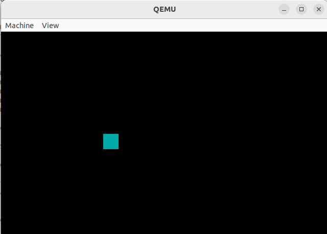
Drawing Rectangle
To draw a rectangle using x, y coordinates for the top-left corner, and width and height dimensions.
; Set up basic graphics mode (320x200, 256 colors) in BIOS bootloader

BITS 16            ; 16-bit real mode
ORG 0x7C00         ; Bootloader entry point

start:
	mov ax, 0x0013 ; Set video mode 0x13 (320x200, 256 colors)
	int 0x10       ; BIOS interrupt to set video mode

    ; Draw a rectangle with top-left corner at (100, 100), width 50, height 30, with color 0x0F (white)
	mov al, 0x03	 ; Color (white)
	mov cx, 100	 ; X coordinate of top-left corner
	mov dx, 100	 ; Y coordinate of top-left corner
	mov si, [width] 	; Width of the rectangle
	mov di, [height]	; Height of the rectangle

	call draw_rectangle

    jmp $          ; Infinite loop

; Function to draw a rectangle with top-left corner at (CX, DX), width SI, height DI, with color AL
draw_rectangle:
    pusha
draw_row:
    call draw_pixel
    inc cx         ; Move to the next pixel in the row

	dec si		; Decrement the width by one
	cmp si, 0	; Check if we reached the end of the row that complete width
    je next_row		; if we drawn complete row, jump to next row.
    jmp draw_row	; Continue drawing the row, until the row completely drawn

next_row:
	mov cx, 100	; Initial coordinates of x

	inc dx		; move y to one down
	mov si, [width]	; reset to x to start of the next row.
	dec di		; decrement the height by 1
	cmp di, 0	; check if we height is 0
	je done       ; If yes, we are done
    jmp draw_row   ; Start drawing the next row

done:
    popa
    ret

; Function to draw a pixel at (CX, DX) with color AL
draw_pixel:
    mov ah, 0x0C   ; BIOS function to plot a pixel
    int 0x10       ; BIOS interrupt
    ret

width dw 15	; width of the rectangle
height dw 15	; height of the rectangle

TIMES 510 - ($ - $$) db 0 ; Fill the rest of the bootloader sector with zeros
DW 0xAA55                 ; Boot signature

Leave a comment
Your email address will not be published. Required fields are marked *