Introduction
As we all know that bootloader's main job is to load the operating system's kernel into the memory and transfers control to it. In a system's boot process, the Stage 1 bootloader is the initial piece of software executed after the BIOS (Basic Input/Output System) completes its system checks and identifies the bootable device. This stage is minimalistic and designed to fit within the first 512 bytes of the Master Boot Record (MBR) or a specific boot sector.
A flat binary bootloader is a simplistic form of a bootloader that does not contain any metadata or advanced formatting – it's simply raw machine code. In this tutorial, we'll focus on creating a Stage 1 flat binary bootloader that will print "Welcome to the Stage1" to the screen. This bootloader will operate in real mode, a 16-bit execution mode where the CPU has direct access to memory and I/O ports, which makes it suitable for early-stage system initialization.
Stage 1 is extremely minimalistic by design:
- It must fit entirely within the first 512 bytes of a bootable disk sector
- It runs without an operating system
- It executes in 16-bit real mode
- It has no access to filesystem, memory managers, or drivers
Because of these constraints, Stage 1 bootloader are often written as flat binaries – raw machine code without headers or metadata.
Prerequisites
Read this Article for understanding the proper boot up process of x86.
📜 Theory
When a computer is turned on, a series of events occur to initialize the hardware, load the operating system, and prepare the system for user interaction. Here's a simplified overview of the boot process:
1️⃣ Power is Applied:
Power Supply Unit (PSU)
- You press the power button
- The motherboard signals the PSU (
PS_#) - PSU converts AC -> regulated DC:
- +12V
- +5V
- +3.3V
- PSU checks voltage stability
Only when power is stable does it assert PWR_OK.
2️⃣ CPU comes out of reset
- CPU was held in reset state
- Once
PWR_OKis received:- CPU reset line is released
- CPU starts executing instructions
- Important:
- CPU does not start from RAM
- RAM is empty at power-on
Instead:
- CPU instruction pointer is hard-wired
x86 CPUs start at:
CS:IP = FFFF:0000 Physical address = 0xFFFFFFF0- This address maps to firmware ROM / flash
This is how the CPU knows where to begin
3️⃣ Firmware execution (BIOS / UEFI)
The code at that address is firmware, stored in:
- SPI flash chip on motherboard
First instruction does:
- Setup minimal CPU state
- Disable caches (initially)
- Switch CPU into a known execution mode
4️⃣ Power-On Self-Test (POST):
Firmware performs hardware initialization & validation.
- The computer's Basic Input/Output System (BIOS) performs a Power-On Self-Test (POST) to check the integrity of hardware components such as the CPU, memory (RAM), storage devices, and input/output devices.
- Any detected errors are reported to the user via audio signals (beeps) or visual codes (error messages on the screen).
5️⃣ BIOS Initialization:
- After the POST completes successfully, the BIOS initializes the hardware components based on the settings stored in the BIOS configuration.
- It identifies and initializes devices such as the keyboard, mouse, display, and storage devices (hard drives, SSDs, etc.).
- The BIOS also locates the bootloader, which is stored in a specific location on the storage device (e.g., the Master Boot Record or EFI System Partition).
For legacy BIOS boot, this means reading sector 0 from the boot disk.
6️⃣ Bootloader Execution:
- The BIOS loads and executes the bootloader code from the designated storage location (e.g., the Master Boot Record or EFI System Partition).
- The process is as follows:
- For MBR:
- The BIOS loads the first sector of the disk at location
0x7c00. - Check its boot signature, it should be
0xAA55. - If it is valid Boot code then jumps at the location
0x7c00and pass the control to it. - From this point onward, BIOS is no longer in control – your code is.
- The BIOS loads the first sector of the disk at location
- For MBR:
🔰 Flat Binary Bootloader
A flat binary bootloader refers to a bootloader that is stored as a raw binary file without any metadata, headers, or extra formatting typically found in more complex executable file formats like ELF or PE. The code is directly written to the boot sector of a bootable device, and the BIOS loads it into memory exactly as-is, without any additional processing.
A flat binary bootloader is a raw sequence of bytes that:
- Contains no executable headers
- Has no relocation information
- Is loaded at a fixed memory address
- Is executed directly by the CPU
Unlike ELF or PE binaries:
- There is no loader
- No symbol resolution
- No metadata
This BIOS simply:
Copies -> checks signatures -> jumps
Here are the key characteristics of a flat binary bootloader:
- No Metadata or Headers: Unlike other executable formats, which include headers with information such as code entry points, file size, or sections, a flat binary bootloader consists only of machine code and data. This makes it extremely simple but also places more responsibility on the programmer to correctly manage the bootloader's structure.
- Fixed Loading Address: The BIOS loads the flat binary bootloader into a predefined location in memory (typically
0x7C00forStage 1bootloaders). The bootloader must assume that its starting point is this specific memory address. - Direct Execution: The bootloader is executed directly by the CPU once it is loaded into memory, without any operating system or external assistance. It operates in real mode (16-bit) on x86 systems, where it can directly access hardware via BIOS interrupts.
- Raw Machine Code: Since it’s a flat binary, the bootloader is pure machine code. There is no need for a linker or complex compilation steps other than assembling the code and copying it directly to the boot sector.
Why Flat Binary Is Required at Stage 1
At this point in boot:
- No filesystem exists
- No dynamic memory allocation
- No virtual memory
- No loader capable of parsing formats like ELF
Therefore, the firmware can only execute raw machine code.
Stage 1 Bootloader Responsibilities
Typical Stage 1 responsibilities include:
- Establish a predictable CPU environment
- Initialize segment registers
- Set up safe stack
- Perform minimal I/O
- Load Stage 1 (optional)
In our case, Stage 1 will only:
- Print a welcome message
- Enter an infinite loop
Stage 1 Code:
Stage 1 bootloaders are responsible for initializing the environment, setting up essential components, and loading subsequent stages of the bootloader or the operating system kernel. However our stage 1 is very simple it will just print welcome message to the screen and go to the infinite loop of doing nothing.
- The BIOS stage 1 bootloader must be 512 bytes in size, which is the size of a single sector on a traditional storage device. This restriction arises because the BIOS, during the start-up process, reads just the first sector (512 bytes) from the boot device and loads it into memory at address
0x7C00.
The 512-Byte Constraint
The BIOS design dates back to early PCs where disk reads were expensive. To keep boot time short and firmware simple:
- BIOS reads only one sector
- Sector size = 512 bytes
| Offset | Size | Purpose |
|---|---|---|
| 0x000 | 510 | Boot code + data |
| 0x1FE | 2 | Boot signature (0x55AA) |
Any code beyond this will never be loaded.
Here’s a breakdown of the 512-byte size constraint:
- Bootloader code: The first 510 bytes (
0x000to0x1FD) are used for the bootloader’s machine code. This is where the actual logic of the bootloader resides. - Boot signature: The last 2 bytes (
0x1FEand0x1FF) must contain the boot signature0x550xAA, which indicates to the BIOS that the sector is valid and bootable.
Thus, you have a total of 510 bytes available for your bootloader's code and data. This tight constraint means that the Stage 1 bootloader has to be highly optimized and perform only the minimal necessary tasks, such as printing "Welcome to stage 1!" or loading a more complex Stage 2 bootloader from disk.
Stack Setup:
For in depth understanding of stack in assembly language please refer to this article: https://thejat.in/learn/understanding-stack-in-assembly
The first thing to always remember about the stack is that it grows downward in memory.
Setting up the stack segment in x86 assembly involves defining and initializing the stack segment (SS) and the stack pointer (SP/ESP/RSP) registers. These registers are crucial for managing the stack, which stores function call information, local variables, return addresses, and other temporary data.
What Happens If We Don't Set Up Stack Segment ❔
- Upon booting, the BIOS typically loads the bootloader at memory address
0x7C00, but the stack segment (SS) and stack pointer (SP) are undefined or retain their values from the previous state. - Often,
SSdefaults to0x0000(or a different BIOS-supplied value) andSPcould point to an unknown location in memory. If you try to perform stack operations likePUSHorCALL, the CPU will use the incorrect or unknown segment and address for stack operations. - Without initializing
SSandSP, these operations will reference an arbitrary memory location, which can lead to corrupted data, overwriting important parts of memory, or crashes (often manifested as a Triple Fault in real mode, which reboots the system). - If the stack pointer (
SP) starts at an unpredictable location (e.g., a location outside the available memory), pushing and popping values from the stack could overwrite critical parts of memory, such as your bootloader code, variables, or even hardware areas like the BIOS data area (BDA). - For example, if
SSis0x0000andSPis0x0200, the stack operations will start at0x0000:0200in memory. This might overwrite interrupt vectors or other important data structures in low memory.
Why Proper Stack Setup is Important ❔
- Safe Stack Operations: By explicitly setting
SS(the stack segment) andSP(the stack pointer), you ensure that the CPU uses a safe, known memory region for stack operations (push, pop, call, ret). - Program Stability: A properly configured stack ensures that function calls and returns are handled properly and that local variables and registers pushed onto the stack are stored and restored safely.
What Happens If You Skip Setting SS and SP ❔
- Unpredictable Stack Behavior: Without properly setting
SSandSP, stack operations will occur at random memory locations. This can lead to:- Crashing: Stack operations might corrupt critical memory regions, causing the system to crash.
- Overwriting Important Data: Data critical to the functioning of the bootloader or even the BIOS (interrupt vectors, BIOS data area) could be overwritten, leading to unpredictable behavior or system instability.
- Corrupted Execution: Since the stack is used to store return addresses for function calls (
CALLandRET), a corrupted stack can lead to incorrect return addresses and incorrect code execution flow.
Different Ways to set up the Stack Segment:
1️⃣ Setting the Stack Segment and Pointer to a Specific Location in Memory
In this approach, you manually choose a specific memory address for the stack segment and stack pointer. This method is often used in simple bootloaders or low-level system code where you have full control over memory layout and know exactly where your stack will reside.
start:
    ; Set SS to 0x0000 and SP to 0x7C00
    ; This means the stack will start at memory location 0x7C00 and grow downward
    xor ax, ax              ; AX = 0x0000
    mov ss, ax              ; SS = 0x0000 (Stack segment at base of memory)
    mov sp, 0x7C00          ; SP = 0x7C00 (Stack starts at 0x7C00)

    ; Stack is now set up at the top of the bootloader
    ; Push and pop instructions can safely be used now

    push ax                 ; Push 0x0000 onto the stack
    pop ax                  ; Pop 0x0000 from the stack (into AX)
Explanation:
- SS = 0x0000: The stack segment is set to the beginning of memory (segment 0).
- SP = 0x7C00: The stack pointer is set to
0x7C00, which is where the BIOS loads the bootloader. This means the stack grows downward from the end of the bootloader.
In this case, you manually choose the stack's memory location, ensuring that it doesn’t overlap with your code or data.
Advantages:
- Simple: This is a straightforward way to set up the stack. You know exactly where the stack is located.
- Direct control: You have complete control over where in memory the stack resides.
Disadvantages:
- Manual management: You have to ensure that the stack doesn't conflict with your code or data.
- No automatic memory reservation: You aren’t reserving specific space for the stack; you're just pointing the stack pointer to a predefined address.
2️⃣ Reserving Space for the Stack and Setting SS to Point to It:
In this approach, you reserve a specific section of memory (either in .bss or as part of the data section) for the stack. Then, you set the SS and SP to point to the reserved memory area. This method is used when you want more explicit control over memory, especially in more complex programs where data, code, and stack are explicitly separated.
section .bss          ; BSS section where we reserve uninitialized space
stack_space resb 512   ; Reserve 512 bytes for the stack (can be any size you want)

section .text         ; Code section begins here

start:
    ; Set up the stack segment and stack pointer
    cli               ; Clear interrupts while setting up the stack

    mov ax, stack_space
    mov ss, ax        ; Set the Stack Segment (SS) to the start of reserved space
    mov sp, 512       ; Set Stack Pointer (SP) to 512 (the end of the reserved stack space)

    sti               ; Re-enable interrupts

    ; Rest of your bootloader code goes here

    jmp $             ; Infinite loop (for bootloader to halt)
Explanation:
- Reserve Stack Space with
resb:- In the
.bsssection (uninitialized data), we useresb 512to reserve 512 bytes of memory for the stack. The labelstack_spacerefers to the beginning of this reserved space. - The size (512 bytes here) can be adjusted depending on how much stack space your bootloader or program needs.
- In the
- Stack Setup:
- CLI: Disable interrupts while setting up the stack to avoid potential issues.
- We load the address of
stack_spaceinto theAXregister and then move it into theSSregister. This sets the Stack Segment (SS) to the beginning of the reserved space. - We set the Stack Pointer (SP) to the size of the reserved stack space (
512), meaning the stack starts from the end of the reserved space and grows downwards. The stack grows downward, so by settingSPto512, the stack will use the memory within the reserved block fromstack_spacetostack_space + 512. - STI: Re-enable interrupts after the stack is set up.
- Why This Works:
- The
resbdirective ensures that the space reserved for the stack is not overwritten by other data or code. - The stack pointer (SP) is initialized to
512, which points to the top of the reserved space, and the stack grows downward as data is pushed onto the stack.
- The
Visualization:
Let's say stack_space is located at memory address 0x7000. After the setup, the memory layout would look like this:
Address        Data
------------------------
0x7200         <-- SP (stack starts here)
...
0x7000         <-- SS (start of stack_space)
Here, the stack pointer (SP) initially points to 0x7200, and as the stack grows downward, it will use the memory within the stack_space block that was reserved using resb.
This approach ensures that the stack has dedicated, reserved space in memory, keeping it safe from potential memory overwrites from other parts of the bootloader.
Stage1.asm:
; 16 Bit Code, Origin at 0x0
BITS 16
ORG 0x7C00

main:
	; Disable Interrupts, unsafe passage
	cli

	; Far jump to fix segment registers
	jmp 	0x0:FixCS	; CS is reloaded

FixCS:
	; Fix segment registers to 0
	xor ax, ax
	mov	ds, ax
	mov	es, ax

	; Set stack
	; The sp register is used to point to the top of the stack. By setting sp to 0x7C00, the bootloader ensures that the stack starts at the top of the memory allocated for the bootloader. This is important because the stack grows downward in memory, so it's set up before any other code runs.
	mov	ss, ax
	mov	ax, 0x7C00	; It ensure that there's space for the stack to grow downward without overlapping with other code or any other data in memory.
	mov	sp, ax

	; set interrupts
	sti

	; Save the DL register value, which contains the disk number
	mov 	byte [bPhysicalDriveNum], dl

	;Print Welcome to the Screen
	mov si, WelcomeToStage1		; Load the address of the string into si register
	call PrintString16BIOS		; String printing function.

	; Infinite loop
	jmp $


; ********************************
; PrintChar
; IN:
; 	- al: Char to print
; ********************************
PrintChar:
	pusha			; Save all registers

	; Setup INT
	mov 	ah, 0x0E	; Function to print character
	mov 	bx, 0x00	; Video page number
	int 	0x10		; BIOS interrupt for video services

	; Restore & Return
	popa			; Restore all saved registers
	ret			; Return from function

; ********************************
; PrintNumber
; IN:
; 	- EAX: NumberToPrint
; ********************************
PrintNumber:
	; Save state
	pushad			; Save all registers

	; Loops
	xor 	bx, bx		; Clear BX register
	mov 	ecx, 10		; Set loop counter

	.DigitLoop:
	    xor 	edx, edx	; Clear EDX register
	    div 	ecx		; Divide eax by 10

	    ; now eax <-- eax/10
	    ;     edx <-- eax % 10

	    ; print edx
	    ; this is one digit, which we have to convert to ASCII
	    ; the print routine uses edx and eax, so let's push eax
	    ; onto the stack. we clear edx at the beginning of the
	    ; loop anyway, so we don't care if we much around with it

	    ; convert dl to ascii
	    add 	dx, 48		; Convert digit to ASCII

	    ; Store it
	    push 	dx		; Push ASCII digit
	    inc 	bx		; Increment counter bx

	    ; if eax is zero, we can quit
	    cmp 	eax, 0		; Compare EAX with 0
	    jnz 	.DigitLoop	; If not zero, loop

	.PrintLoop:
		pop 	ax		; Pop ASCII digit from stack

		; Print it
		call 	PrintChar	; Print character

		; Decrease
		dec 	bx		; Decrease counter BX
		jnz 	.PrintLoop	; If not zero, loop

    ; Done
    popad	; Restore all saved registers
    ret		; Return from function


; ********************************
; Print String 16 BIOS
; Prints the string in real mode using BIOS function.
; IN:
; 	- ESI: Null Terminated String
; ********************************
PrintString16BIOS:
	pusha		; pusha all register on stack
	mov ah, 0x0E	; BIOS teletype function
.print_string_16_bios_loop:	; label for loop
	lodsb			; Load byte at [SI] into AL and increment SI
	test al, al		; Perform bitwise AND of AL with itself to set flags
	jz .print_string_16_bios_done	; If zero flag is set (AL was zero), jump to done
	int 0x10			; Call BIOS interrupt
	jmp .print_string_16_bios_loop	;  Repeat for the next character
.print_string_16_bios_done:		; Label for the printing done
	popa				; Pop all the saved registers
	ret				; return from the function

; **************************
; Variables
; **************************
bPhysicalDriveNum	db	0	; Define variable to store disk number

WelcomeToStage1	db 'Welcome to the Stage1', 0	; Define welcome message

; Fill out bootloader
times 510-($-$$) db 0		; Fill up the remaining space with zeroes

; Boot Signature
db 0x55, 0xAA		; Boot signature indicating valid bootloader
Explanation:
ORG Directive:
- The code starts with the declaration of the environment as
16-bit codeand sets the origin (ORG) to0x7C00, indicating where the bootloader code will be loaded in memory.- The value given to the
ORGdirective acts as an offset, indicating the address at which subsequent code or data will be located.
- The value given to the
The ORG directive in assembly is used to specify the origin or starting address of the code in memory. It ensures that all labels and memory addresses within the code are calculated relative to this starting address. Without the ORG directive, the assembler would assume the code starts at address 0x0000, which might lead to incorrect memory references and jumps when the code is actually loaded into a different location in memory.
For example, in the context of a bootloader, the BIOS loads the bootloader at the memory address 0x7C00. By using the ORG 0x7C00 directive, you are telling the assembler that the code will be loaded at 0x7C00, and any labels or addresses within the code will be calculated from this origin. This is critical for ensuring that jump instructions, memory accesses, and data references point to the correct locations in memory when the bootloader is executed.
[BITS 16]         ; We're working in 16-bit real mode
[ORG 0x7C00]      ; Tell the assembler that code starts at 0x7C00

start:
    mov si, hello_msg   ; SI now points to the string "Hello, World!"
    call print_string   ; Print the message

hello_msg db 'Hello, World!', 0  ; Null-terminated string

times 510 - ($ - $$) db 0        ; Fill remaining space up to 510 bytes
dw 0xAA55                        ; Boot signature (0x55, 0xAA)
In this example:
- The
ORG 0x7C00ensures that when the BIOS loads this code into memory at address 0x7C00, the assembler calculates the offsets ofhello_msgandprint_stringrelative to 0x7C00, not 0x0000. - Without
ORG 0x7C00, the labels would be offset incorrectly, leading to unexpected behavior when the bootloader runs.
main:
- The
mainfunction begins by disabling interrupts (cli) to ensure a safe passage during execution. - It then performs a far jump to the
FixCSfunction to fix the segment registers. - The
FixCSfunction clears the segment registers (DS, ES) to 0, ensuring proper memory addressing. - It sets up the stack by loading the stack pointer (SP) with the address 0x7C00, ensuring there's space for the stack to grow downward without overlapping with other code or data.
- Interrupts are re-enabled (
sti) after setting up the environment, allowing the system to handle external events such as hardware interrupts. - The code saves the value of the DL register, which contains the disk number, into the
bPhysicalDriveNumvariable. - It then prints the welcome message "Welcome to the Stage1" to the screen using the
PrintString16BIOSfunction. - Printing Functions:
- The code includes three printing functions:
PrintChar,PrintNumber, andPrintString16BIOS. PrintCharprints a single character,PrintNumberprints a number, andPrintString16BIOSprints a null-terminated string using BIOS interrupt0x10for video services.
- The code includes three printing functions:
- Variables and Boot Signature:
- The code defines a variable
bPhysicalDriveNumto store the disk number and a welcome message stringWelcomeToStage1. - Finally, it includes a boot signature (
0x55,0xAA) at the end of the bootloader code, indicating to the BIOS that it's a valid bootloader.
- The code defines a variable
Why DL Matters
BIOS Sets DL to:
Ox00: floppyOx80: first hard disk
Saving it enables:
- Disk reads later (Stage 2 loader)
- Multi-disk support
BIOS Interrupt Usage
Using:
int 0x10
Is correct and idiomatic for early boot.
But note:
- BIOS interrupts will not work once you leave real mode
- Later stages must use direct hardware access
Compilation:
# $@ = target file
# $< = first dependency
# $^ = all dependencies

all: build_dir stage1.bin

build_dir:
	mkdir -p build

stage1.bin: boot/stage1/stage1.asm
	nasm -f bin -o build/$@ $<

disk.img:
	@echo "Creating the disk image..."
	dd if=/dev/zero of=build/disk.img bs=512 count=2880  # Creates a 1.44MB floppy disk image
	dd if=build/stage1.bin of=build/disk.img conv=notrunc  # Writes the bootloader to the first sector
	@echo "Disk image 'build/disk.img' created successfully."

run:
	qemu-system-x86_64 -drive  format=raw,file=build/stage1.bin

# Clean up generated files
clean:
	rm -rf build
all: build_dir stage1.bin:
- This is the default target of the Makefile, which means running just
makewithout any arguments will execute these commands. - It depends on two targets:
build_dirandstage1.bin.
build_dir::
- This is a phony target (a target that doesn't represent a file) used to create a directory named
buildwhere the output files will be stored. - The command
mkdir -p buildcreates the directory if it doesn't exist (-p flag ensures no error if the directory already exists).
stage1.bin: boot/stage1/stage1.asm:
- This target is responsible for assembling the Stage 1 bootloader source code (
stage1.asm) located in theboot/stage1directory. - It uses NASM (Netwide Assembler) with the
-f binoption to generate a flat binary output (-f specifies the output format). - The output binary file is saved in the
builddirectory with the namestage1.bin.
run::
- This target is used to run the generated bootloader using QEMU, an emulator for various CPU architectures.
- It executes the command
qemu-system-x86_64 -drive format=raw,file=build/stage1.bin, which launches QEMU with the generatedstage1.binfile as the disk image in raw format.
disk.img:
- We can optionally create a disk image. We can run the boot code without building
disk.imgfile but we would need it later on.
dd if=/dev/zero of=build/disk.img bs=512 count=2880 # Creates a 1.44MB floppy disk image
This command creates a 1.44MB floppy disk image filled with zero bytes (0x00). It does this by writing 2880 blocks, each 512 bytes in size, of zero bytes to build/disk.img.
- Parameters:
dd: The command used for low-level copying and conversion of raw data.if=/dev/zero: Specifies the input file./dev/zerois a special file in Unix-like operating systems that provides as many null (zero value) bytes as are read from it.of=build/disk.img: Specifies the output file. Here,build/disk.imgis the name of the disk image being created. This file will be located in thebuilddirectory.bs=512: Sets the block size to 512 bytes. This is the standard sector size for floppy disks.count=2880: Specifies the number of blocks to write. Since a standard 1.44MB floppy disk has 2880 sectors of 512 bytes each, this creates a 1.44MB disk image.
dd if=build/stage1.bin of=build/disk.img conv=notrunc
This command writes the bootloader (contained in build/stage1.bin) to the first sector of the disk image (build/disk.img). The bootloader typically fits within the first 512 bytes, the size of one sector.
- Parameters:
dd: The command used for low-level copying and conversion of raw data.if=build/stage1.bin: Specifies the input file.build/stage1.binis the compiled bootloader binary.of=build/disk.img: Specifies the output file. In this case, it's the disk image we created in the previous step.conv=notrunc: This conversion option tellsddnot to truncate the output file. By default,ddmight truncate the output file to match the size of the input file.notruncensures that the disk image remains 1.44MB and only the specified input data (the bootloader) is written at the beginning.
- Additional
ddParameters which would be helpful in future lessons.skip=N: Skip N blocks (ofbssize) from the input file before copying.seek=N: Skip N blocks (ofbssize) from the output file before writing.count=N: Copy only N input blocks.bs=BYTES: Set both input and output block size to BYTES.iflag=FLAGS: Read-specific flags (e.g.,direct,fullblock).oflag=FLAGS: Write-specific flags (e.g.,append,sync).
clean::
- This target is used to clean up the generated files.
- It removes the
builddirectory and all its contents recursively using the commandrm -rf build.
Variables Used:
$@: Represents the target filename (e.g.,stage1.bin).$<: Represents the first dependency filename (e.g.,boot/stage1/stage1.asm).$^: Represents all dependencies (e.g.,boot/stage1/stage1.asm).
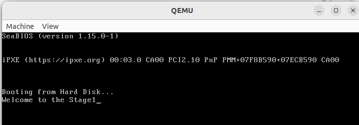
Output:
📜 Knowledge Center:
Repository:
The whole code is committed in the Github repository, Below is the link for it:
https://github.com/The-Jat/TheTaaJ/tree/b4e45d32b61bc0ec024b456dac619e852df906f3

Join the discussion
Sign in with your account to post comments, reply to others, and participate in the conversation.
Login to Comment