Up to this point we are working in the real mode, and we are familiar with the limitations of the real mode.
1. Memory Addressing Limitation
- 20-bit Addressing:
- Real Mode can only address up to 1 MB of memory using 20-bit addresses. This is due to its segment addressing scheme, where the segment register is shifted left by four bits and added to the offset.
- As a result, the maximum addressable memory space is
2^20=1,048,576bytes, or 1 MB, which is insufficient for modern applications and operating systems.
- Fixed Segment Size:
- Segments in Real Mode are fixed at
2^16=65,536bytes =64KB. This means that each segment can only span 64 KB of memory, limiting the size of code and data that can be efficiently managed within a single segment.
- Segments in Real Mode are fixed at
2. Lack of Protection
- No Memory Protection:
- In Real Mode, all programs have unrestricted access to all memory and hardware. This lack of protection means that one program can easily overwrite the memory of another program or even the operating system, leading to system instability and crashes.
- No Privilege Levels:
- Real Mode does not support privilege levels (rings), so there is no distinction between user and kernel modes. This makes it impossible to enforce security policies or isolate critical system components from user applications.
3. No Multitasking Support
- Single Tasking:
- Real Mode does not support hardware-based multitasking. Any multitasking must be implemented by the operating system in software, which is less efficient and more prone to errors.
- This limits the ability to run multiple applications simultaneously and efficiently manage system resources.
4. Limited Interrupt Handling
- Simple Interrupt Vector Table:
- Interrupt vectors in Real Mode are stored in a fixed location in memory (the first 1 KB of address space). This limits the flexibility and complexity of interrupt handling.
- Advanced interrupt handling features, such as prioritization and nested interrupts, are difficult to implement.
5. No Advanced Memory Management
- No Virtual Memory:
- Real Mode does not support virtual memory. All memory accesses are direct physical addresses, which limits the ability to implement features like paging or memory protection.
- This restricts the ability to use disk space to extend physical memory, reducing the effective memory available for applications.
6. Limited Instruction Set
- No Support for 32-bit Instructions:
- Real Mode only supports 16-bit instructions and registers. While some 32-bit operations can be performed using segment overrides and other techniques, these are cumbersome and inefficient.
- This limits the performance and capabilities of software running in Real Mode, especially for tasks that require significant computational power or large data sets.
7. Inefficient Use of Modern Hardware
- No Access to Advanced CPU Features:
- Modern CPUs include features like hardware virtualization, advanced power management, and security features that are not accessible in Real Mode.
- This results in underutilization of the capabilities of modern processors, leading to less efficient and secure system operation.
Protected mode overcomes all of these limitation, It was introduces with Intel 80286 processor which was a 16-bit processor but supported 24-bit addressing in Protected mode, allowing it to access up to 16 MB of memory, which was a significant increase over the 1 MB limit in Real Mode.
The first true 32-bit processor in the x86 family was the Intel 80386 (i386), introduced in 1985. The 80386 expanded the capabilities of Protected Mode to include 32-bit addressing and 32-bit data operations, further enhancing the performance and capabilities of x86 systems.
Enabling Protected Mode
In order to enable the protected mode, there are some things which needs to be done before and we have already did those.
- Enabling A20 Gate: We have enabled A20 already, which let us address the whole memory available to the system.
- Learn more about it here: https://thejat.in/learn/enable-a20-gate
- Setting Up 32-bit GDT: We have already Set the Global Descriptor Table (GDT), which is a kind of security mechanism for the memory in protected mode.
- Learn more about it here: https://thejat.in/learn/installing-32-bit-gdt
If you have done all these steps then we can proceed to enable the Protected Mode.
1️⃣ Enable The Protection Enable (PE) Bit in CR0
The PE bit is located in the Control Register 0 (CR0) and its primary role is to enable or disable Protected Mode.
Location and Role of the PE Bit
- Register: CR0 (Control Register 0)
- Bit Position: Bit 0
When the PE bit is set to 1, the CPU operates in Protected Mode. When it is cleared (set to 0), the CPU operates in Real Mode.
Setting the PE Bit
To enable Protected Mode, the PE bit in the CR0 register must be set. This is typically done in a Stage 2 bootloader during the system boot process.
Here is the code snippet of doing so:
; Enable Protected Mode
    mov eax, cr0        ; Move the current value of CR0 register into eax
    or eax, 0x1         ; Set PE bit (bit 0) to 1
    mov cr0, eax        ; Write the modified value back to the CR0 register,
                        ; enabling Protected Mode
We have to place this code in our stage2.asm file. Just after the code in which we load the kernel in in our last chapter. This time we don't jump to the kernel yet because our kernel is of 16-bit and we are shifting to 32-bit mode, so we need to change our kernel to 32-bit mode which we will do later on.
2️⃣ Do Far Jump to Clear Prefetch Queue
After enabling the Protection Enable (PE) bit in the CR0 register to switch from Real Mode to Protected Mode, a far jump is necessary. This far jump serves a critical role in ensuring that the CPU fully recognizes the mode switch and correctly uses the new segment descriptors defined in the Global Descriptor Table (GDT).
Reasons for the Far Jump:
1 Flushing the Instruction Prefetch Queue:
- When the PE bit is set, the CPU may still have instructions from Real Mode in its prefetch queue. A far jump clears this queue, ensuring that the CPU fetches the next instructions in Protected Mode, using the new segment descriptors and addressing.
2 Loading the Correct Segment Descriptor:
- In Real Mode, segment registers contain actual segment addresses shifted by four bits (e.g., the
csregister contains the base address of the code segment). In Protected Mode, these registers contain selectors that index into the GDT to get the segment base address, limit, and access rights. - A far jump forces the CPU to reload the code segment (
cs) register with the new segment selector, effectively switching the context to the new segment descriptor defined in the GDT.
How It Works
A far jump in x86 assembly language includes both a segment selector and an offset. This format forces the CPU to:
Reload the Segment Selector:
- The segment selector is an index into the GDT. By providing a new segment selector in the far jump, the CPU knows to use the Protected Mode segment descriptor.
Set the Instruction Pointer:
- The offset part of the far jump specifies the new value for the Instruction Pointer (
eiporip), which tells the CPU where to continue execution within the new segment.
Code for Far Jump:
    ; Perform a far jump to clear the prefetch queue
    jmp 0x08:ProtectedMode  ; Segment selector 0x08 (code segment)

BITS 32
ProtectedMode:

    ; Update segment registers
    xor eax, eax
    mov ax, 0x10              ; Data segment selector 0x10
    mov ds, ax
    mov es, ax
    mov fs, ax
    mov gs, ax
    mov ss, ax

    mov esp, 0x7BFF     ; set the stack top to the 0x7BFF
                        ; The stack grows from high memory to lower memory
    					;  --------
    					;  |______| 0x7BFF
    					;  |______|
    					;  |......|  it is growing downward
    					;  |______|	 as we pushes data
    					;  |______|
    					;  |      | 0x7AFF

    ; Disable all irq lines
	mov 	al, 0xff
	out 	0xa1, al
	out 	0x21, al

    cli			; Disable the interrupt as they are no more available
    			; in real mode.

    ; Now we are in protective land

    ;; Test by Printing character to direct VGA memory
    ; The first byte at this location is for character to print
    ; The next byte is for the color
    mov esi, 0xb8000	; VGA memory address
	mov byte [esi], 'P'
	mov byte [esi+1], 0x07

	mov byte [esi+2], 'r'
	mov byte [esi+3], 0x07

	mov byte [esi+4], 'o'
	mov byte [esi+5], 0x07

	mov byte [esi+6], 't'
	mov byte [esi+7], 0x07

	mov byte [esi+8], 'e'
	mov byte [esi+9], 0x07

	mov byte [esi+10], 'c'
	mov byte [esi+11], 0x07

	mov byte [esi+12], 't'
	mov byte [esi+13], 0x07

	mov byte [esi+14], 'e'
	mov byte [esi+15], 0x07

	mov byte [esi+16], 'd'
	mov byte [esi+17], 0x07

	jmp $		; infinite loop
Explanation:
; Perform a far jump to clear the prefetch queue
    jmp 0x08:protected_mode_start  ; Segment selector 0x08 (code segment)
jmp 0x08:protected_mode_start: This far jump instruction includes a segment selector (0x08) and an offset (protected_mode_start). The segment selector0x08points to the code segment descriptor in the GDT. The far jump clears the instruction prefetch queue and ensures the CPU uses the new segment descriptors for execution.
BITS 32BITS 32: This directive tells the assembler that the following code is 32-bit, necessary for Protected Mode.
; Update segment registers
    xor eax, eax
    mov ax, 0x10             ; Data segment selector 0x10
    mov ds, ax
    mov es, ax
    mov fs, ax
    mov gs, ax
    mov ss, ax
Segment Register Initialization:
xor eax, eax: Clear theeaxregister to set the upper 16 bits to 0.mov ax, 0x10: Load the data segment selector (0x10) into theaxregister. The value0x10corresponds to the data segment descriptor in the GDT.mov ds, ax,mov es, ax,mov fs, ax,mov gs, ax,mov ss, ax: Load the segment selectors into the segment registers (ds,es,fs,gs,ss). This step ensures that these registers use the data segment descriptor defined in the GDT.
mov esp, 0x7BFFmov esp, 0x7BFF: Set the stack pointer (esp) to an appropriate address. In this case,0x7BFFis an example address within the available memory range.- The stack grows from higher memory address to lower address in x86.
 ; Disable ALL irq
 lines
	mov 	al, 0xff
	out 	0xa1, al
	out 	0x21, al
mov al, 0xff:mov al, 0xffmoves the immediate value0xff(which is11111111in binary) into thealregister. Here,alstands for the lower 8 bits of theaxregister.
out 0xa1, al:out 0xa1, alis an output instruction that sends the contents of thealregister (0xff) to the secondary PIC (Programmable Interrupt Controller) command port. In x86 systems, the secondary PIC's command port is at I/O port0xa1.
out 0x21, al:out 0x21, alsends the same value (0xfffromal) to the primary PIC command port. The primary PIC's command port is located at I/O port0x21.
The purpose of these instructions is typically related to interrupt handling in x86 systems, specifically in scenarios where you want to mask (disable) interrupts. Here’s what happens in context:
- Interrupt Masking: By setting
alto0xff, which is11111111in binary, you are setting all bits ofalto1. In the context of PICs:- Each bit in
alcorresponds to an interrupt line connected to devices. - Writing
0xffto both PICs (0x21for primary and0xa1for secondary) effectively masks (disables) all interrupts from these devices.
- Each bit in
- Why Mask Interrupts?:
- Masking interrupts is often done during critical sections of code execution where you do not want to be interrupted by hardware interrupts.
- For example, during system initialization, setting
0xffmasks interrupts prevents the CPU from being distracted by peripheral events until it’s ready to handle them.
clicli: This instruction disables interrupts again to ensure that the CPU does not handle any interrupts while the segment registers are being set up.
Output
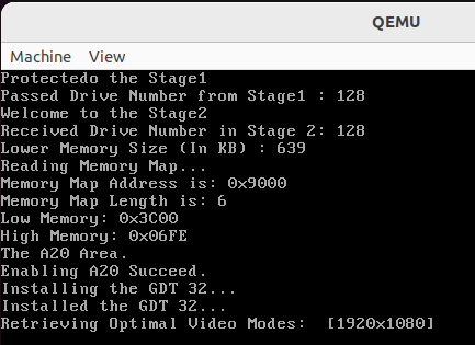
As you can see it is working and printed, Protected to the very starting of the memory 0xb8000.
Source Code:
The source code is available with this particular commit here: https://github.com/The-Jat/TheTaaJ/tree/005c751a022decbb3d2f9a098dc47887587ac179

Leave a comment
Your email address will not be published. Required fields are marked *